
Till now, we have learnt about the Resistor, basically how it works, what its applications are, how to use it in a circuit, etc. But we come across the circuits that involve some combinations of resistors. Our aim in this article is to simplify this network and obtain the equivalent resistance of the network.
1. Types of Resistors:
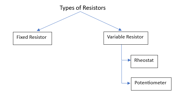
Fixed Value Resistor:
These resistors have their values fixed by the manufacturers themselves. But there can be a slight deflection from the value. We call this deflection ‘tolerance’.

Suppose we have been given a resistor of value ,
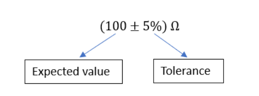
It means the expected value of the resistance is and the Tolerance is 5%
This tells us that the value of the resistor (fixed) can vary from
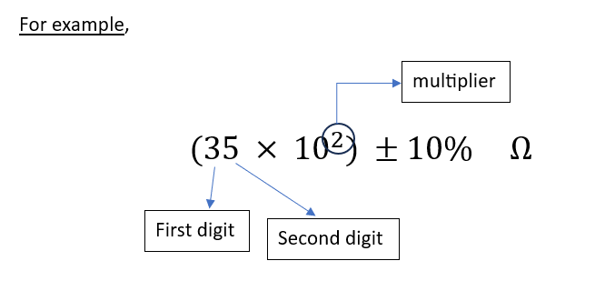
How to calculate the Value of the Resistance? – Color Coding
- The first band gives the first digit
- The second band gives the second digit
- Third band gives the multiplier (the power raised to base 10)
- The fourth band gives you the tolerance value
To clarify even further, we take an example of a fixed resistor having its value of resistance as:
For this, we need to predict the color coding of this resistor. This can be done with the help of the table below, which contains the colors corresponding to their digit, and also tells the tolerance value associated with that color.
| Colour | Number | Tolerance |
|---|---|---|
| Black | 0 | ±20% |
| Brown | 1 | ±1% |
| Red | 2 | ±2% |
| Orange | 3 | ±3% |
| Yellow | 4 | ±4% |
| Green | 5 | – |
| Blue | 6 | – |
| Violet | 7 | – |
| Grey | 8 | – |
| White | 9 | – |
| Gold | 0.1 | ±5% |
| Silver | 0.01 | ±10% |
So, for the above example , the color coding will be:
- First band – Orange
- Second band – Green
- Third band – Red
- Fourth band – Silver
Here’s a tool to make your job of choosing the resistor based on color coding even more easy!
Resistor Color Code Calculator
Select the number of bands and their colors to instantly calculate the resistance.
Resistance Value:
Variable Resistors:
- Resistors, whose value can be altered, are known as Variable Resistors. The manufacturer just prints the maximum value that the device can go up to. (For example, if 10K is printed on a potentiometer, it implies that you can adjust its resistance to any value from 0 to 10K ohms).
- The way you can vary the resistance changes from component to component
2. Power Rating of Resistors:
We have learnt about choosing the value of Resistance but whenever current passes through resistors, there is some heat generated as well. Now, we need to take care that this heat doesn’t damage the resistor. For this, we have power ratings assigned to resistors. Power is basically heat generated per second and is measured in Watts (W)
- There is a relation of power with Voltage and Current,
\(\displaystyle P = V \times I\)
Here, P is the Power (in watts)
V is the potential difference across the resistor (in volts)
I is the current flowing through the resistor (in amperes)
- There are resistors available of 1/8 watt, 1/4 watt, 1/2 watt, 1 watt, etc. The larger the size of the resistor, the higher the power rating it has!
Example:
Suppose the voltage difference across the resistor is going to be 6V, and a current of 20mA is going to pass through it. For the given situation, what should be the suitable power rating of the resistor?
\(\displaystyle P = V \times I\)
\(\displaystyle P = 6 \times (20 \times 10^{-3})\)
\(\displaystyle P = 0.12 W\)
From the above example, we can infer that a resistor of 1/8 W is ‘just’ greater than the power rating of the given resistor. So, we can conclude that it’s safe but still risky!
3. What is meant by finding equivalent resistance ?
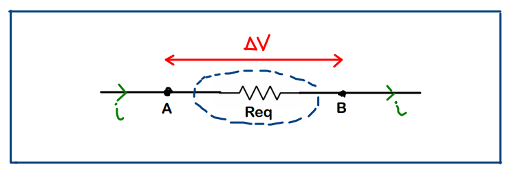
When it comes to circuit solving, we will encounter lot of complex combination of resistors present in the circuit. Finding ‘equivalent’ of such combination of resistors means that, we must be able to replace that whole thing with just a single resistor without changing any of the other parameters (current, potential difference across given points, etc. ) in the circuit.
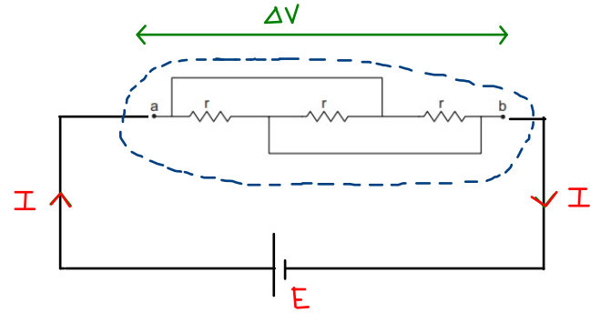
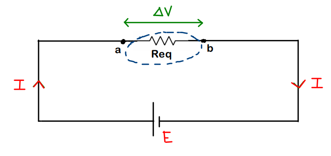
Note that, in Fig.1 (a) and (b), except for the number of resistors, there is no change in other parameters (I remains I, E remains E, V remains V)
Now, how to actually calculate this value of Req is what we need to study in this article
4. Resistors in Series
Resistors are said to be in Series when the current flowing through them is the same. Done!
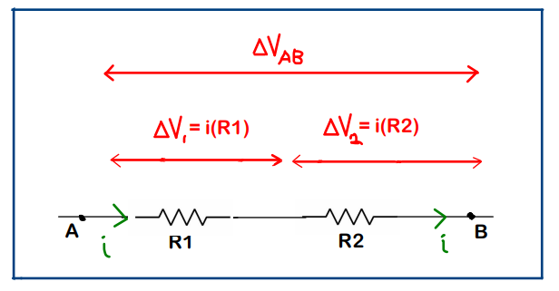
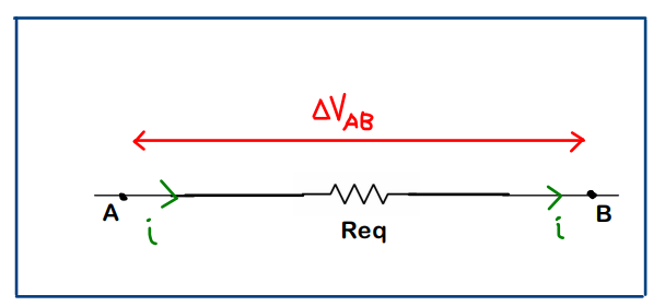
Now, with reference to the above figure,
The voltage drop across Req should be equal to the sum of the voltage drops across R1 and R2, since our main aim is not to disturb the potential difference between points A and B.
\(\displaystyle \Delta V_{AB} = \Delta V_{Req} = \Delta V_1 + \Delta V_2\)
\(\displaystyle iR_{eq} = iR_1 + iR_2 \quad \text{(current remains same)}\)
\(\displaystyle R_{eq} = R_1 + R_2\)
Important Note:
From the above relation, we can infer that we can use series combination if we need a resistance value greater than the individual resistances (i.e., Req > R1 & also Req > R2)
So, Resistors in Series just add up directly!
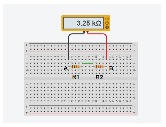
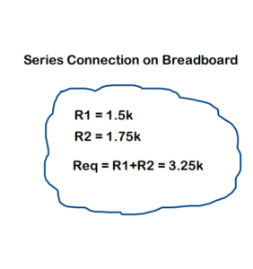
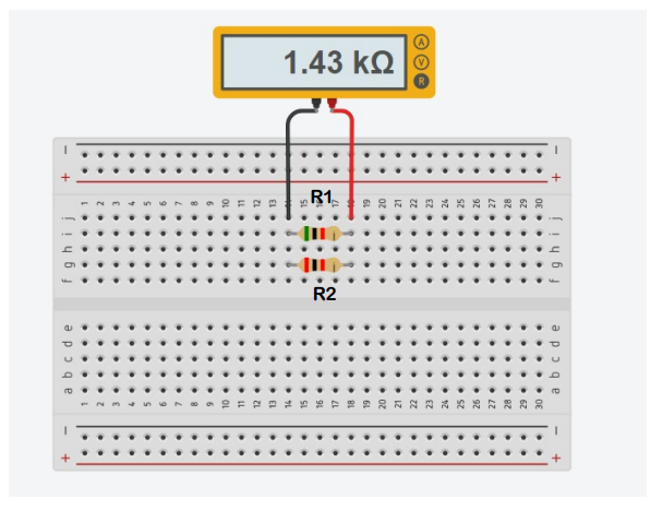
The figure below shows the series combination of R1 and R2 resistors having resistances of 1.5 kΩ and 1.75 kΩ. The equivalent resistance Req in this case is measured by a multimeter in Tinkercad. The value for Req comes out to be 3.25 kΩ
5. Resistors in Parallel
Resistors are said to be in parallel, when they have same potential difference across them. Done!

The potential difference (PD) across Req should also be equal to the potential differences across R1 and R2 (i.e., V), since our main aim is not to disturb the potential difference between points A and B
Here, the quantity that is varying is current, and by applying KCL starting from A, we have the relation,
\(\displaystyle i = i_1 + i_2\)
\(\displaystyle \frac{\Delta V}{R_{eq}} = \frac{\Delta V}{R_1} + \frac{\Delta V}{R_2} \quad \text{(PD remains same)}\)
\(\displaystyle \frac{1}{R_{eq}} = \frac{1}{R_1} + \frac{1}{R_2}\)
Important Note :
From the above relation, we can infer that we can use parallel combination if we need a resistance value even lower than the individual resistances. (i.e. Req < R1 & also Req < R2)
Breadboard Connections for parallel combination (in Tinkercad):

Simulator link: Try out this simulator when you are building some circuits and want to save time on your calculations. Focus on what matters.
6. Example on Series & Parallel Combinations
Question-1
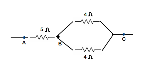
Find the equivalent resistance of the given setup across points A and C
Solution:
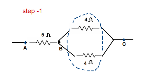
Step – 1: Both the 4 Ω resistors are connected across the same points B and C. Hence, both are in parallel combination. Req for just this combination will be 2 Ω
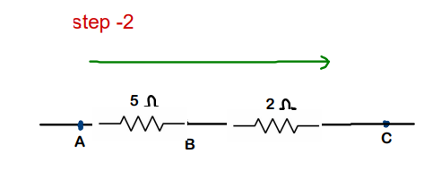
Step-2: Now, 5Ω and 2 Ω are in series combination. Req of this will be 7Ω
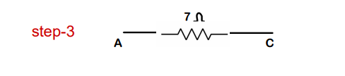
Step-3 : Finally, we have 7 Ω resistor between A and C. This is our final Req between points A and C
Question – 2: Find the effective resistance between points A and B for the figure below
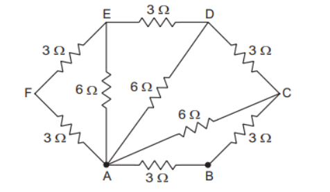
Solution:
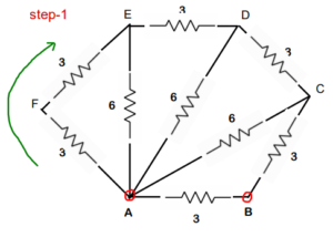
Step 1 : Same current passes through AF and FE, which makes both the 3 ohm resistors in series. Req for this will be 3Ω+3Ω = 6 Ω
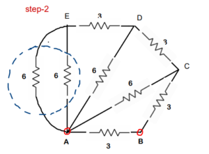
Step 2 : Two 6 Ω resistors are connected across same points A and E which makes them in parallel. Req for this will be 3ohm


Step 3 : Again, both 3 Ω are in series. Req will be 6 Ω
Step 4: Both 6 Ω are in parallel. Req will be 3 Ω


Step-5 : 3 Ω and 3 Ω are in series. Req of this will be 6 Ω
Step-6: two 6 Ω resistors are in parallel. Req of this will be 3 Ω. Keep on simplifying further.
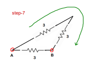
Step-7 : 3 Ω and 3Ω are in series
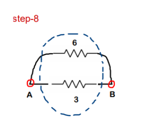
Step-8: 6 Ω and 3Ω are in parallel. Solving this combination, we get Req of this as 2ohms.
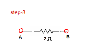
Final Answer : So, the overall equivalent resistance across points A and B is 2 Ω
Conclusion:
Through this article, we tried to learn about resistors and how to perform the basic analysis of circuits involving resistors. According to me, understanding electronics right from the root will be really beneficial.
Learning to deal with Resistors, Capacitors, Inductors, and integrated circuits helps us to build the
The Complete Guide on Resistors:
- Part-1: What Is a Resistor & How to Use It in Circuits
- Part 2 (You are here): Color Coding & Combining Resistors: Series-Parallel Combinations
- Part-3: How to Solve Resistor Networks – Methods & Examples
