RC Airplane Series – Part 1
Finally, after a lot of study regarding this topic, I have made my own RC Airplane from scratch. This series aims to cover the aspects necessary for the modelling of RC aircraft, and I will guide you through this series so that you can design your own RC airplane based on your constraints/requirements.
In this article, we are going to discuss one of the most important aspects of an airplane, i.e., Wings. This is crucial to understand, since there’s no point in building the RC Airplane without understanding how it works!
1. What’s the principle behind Wings?
So, in order to understand how the wings help to generate the lift, we need to know about Bernoulli’s Principle. It states that:
Bernoulli’s Theorem:
“The sum of the pressure, kinetic energy density & the gravitational potential energy density at a point in streamline remains constant“
The mathematical equation for Bernoulli’s Theorem looks as follows:
\(\displaystyle P + \frac{1}{2}\rho v^2 + \rho gh = \text{constant}\)
All this looks a bit complicated, doesn’t it?
But the only thing that we require from this equation, to understand the reasoning, is that:
“As pressure increases, velocity in that region decreases & vice versa is also true.”
\(\displaystyle P \uparrow \quad v \downarrow \quad \text{and} \quad P \downarrow \quad v \uparrow\)
2. Conducting a small activity
What all do we need?
- Two A-4 sheets
- A quiet room (FANS OFF please!)
Procedure:
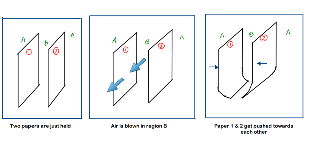
- Hold the 2 papers vertically with each paper in each hand.
- Observe that nothing happens here
- Now, blow air with your mouth into the region B (region between the 2 papers)
- Observe what happens!
Why did this happen?
Note : The region between the 2 sheets is named as ‘B’ while the region except B is called ‘region A’ (i.e. the surroundings to region B)
- Initially, the pressure in region B and A is the same since the velocity of air is same everywhere
- Now, we blow air into the region B (between the sheets). This causes the velocity of air in the region B to increase in comparison to its surroundings (region A)
\(\displaystyle v_B > v_A\)
- Now, by Bernoulli’s principle, we can derive the conclusion that,
\(\displaystyle P_B < P_A\)
- Because of this, the sheets are pushed towards each other by the surroundings due to the relatively higher pressure of the surroundings than that of region B
3. About Airfoil Shape
You can use the interactive airfoil simulator developed by NASA by clicking here.
Now, to use the above results in an application, we have a shape known as ‘Airfoil’ (also called aerofoil). We can describe this shape by its upper and lower surfaces. The upper surface has a curvature known as ‘Camber,’ and the upper surface has a larger length as compared to the lower surface, which is done purposely.
To understand the shape, have a look at the figure below. (I will try improving my drawing skills !!)
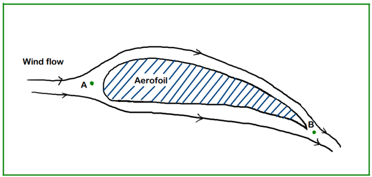
Consider points A and B. At point A, the streamlines diverge to pass over the airfoil and then meet up again at point B. Now, we know that the flow is streamlined and laminar, the air particles flowing over the upper surface have to keep up with the air particles passing under the lower surface.
We already know that the upper surface has a greater length than the lower one. Hence, to meet at B at the same instant, the velocity of air passing over the upper surface has to be greater since it has to cover more distance in the same time.
Hence,
\(\displaystyle v_{upper} > v_{lower}\)
But, by Bernoulli’s principle we know that,
\(\displaystyle P_{upper} < P_{lower}\)
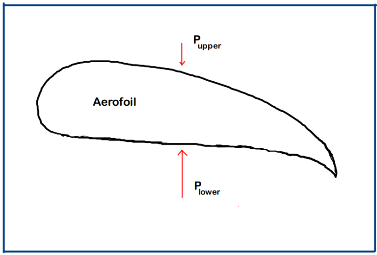
This is how lift is generated & we can see that the airfoil shape has a lot of role to play in this.
4. Some frequently used terms in Aerodynamics
4.1 Leading Edge and Trailing Edge
- The leading edge is the foremost edge of the wing. This is the first part of the wing that comes in contact with the air flow. It is mostly rounded in order to have a smooth airflow over the wing.
- The trailing edge is the rearmost edge of the wing. This is the portion where the airflow leaves the wing. This edge of the wing includes the control surfaces with Ailerons and the Flaps
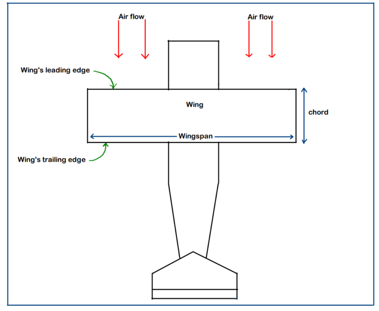
4.2 Chord
The distance (straight line length) between the leading edge and the trailing edge of the wing is called ‘chord’.
It is not always that the wing will be rectangular, so, in that case, we consider the ‘mean’ chord length, which can be calculated based on the shape of the wing.
\(\displaystyle \text{chord } (C) = \frac{\text{WingArea } (S)}{\text{Wingspan } (b)}\)
For rectangular wing, the width of the rectangle becomes the chord.
4.3 Vortex Drag
Now, this is something which comes as a by-product with the ‘Lift’ which we don’t need, and hence we must try to at least minimize it as much as possible.
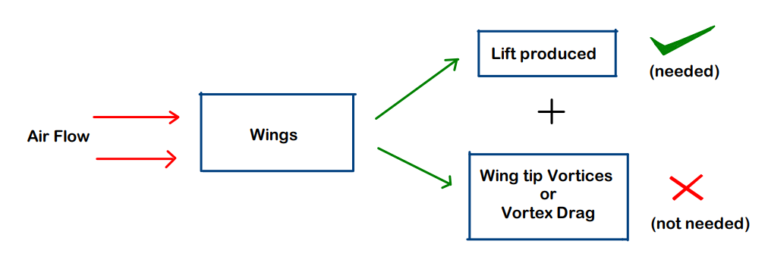
Figure explanation: When the air flows over the Wings, lift is generated & simultaneously, wing tip vortices are also formed, which we need to minimize since it consumes fuel, hence dropping the fuel efficiency of the plane.
When the air flows over the Wings, lift is generated & simultaneously, wing tip vortices are also formed, which we need to minimize since it consumes fuel, hence dropping the fuel efficiency of the plane.
Why does it happen?
The wing is a finite-dimensional part, and hence it will come to an end at some point. This is the point which we call the ‘Wing tip’. Just at the wing tips, there is still a high-pressure region below and a low-pressure region above. This pressure difference causes the air particles to execute a rotational type of motion, which we call ‘vortex.’
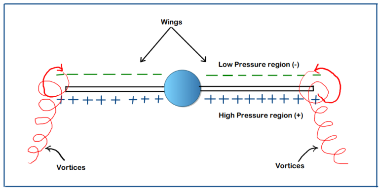
Now due to this,
- The air particles exhibit rotational motion (as we see in the figure)
- But from where do these particles get energy to exhibit this rotational motion
- This energy is extracted from the wings (or indirectly, the part of the fuel is getting consumed to overcome this drag)
- Therefore, we conclude that, the induced drag affects the fuel efficiency of airplane
4.4 Aspect Ratio
Aspect Ratio is defined as the ratio of the wingspan to the mean chord length.
It is one of the most characteristic aspects of the object (here, an airplane), and AR for an aircraft is determined based on the work it is going to be used for.
\(\displaystyle \text{Aspect Ratio } (\text{AR}) = \frac{\text{Wingspan } (b)}{\text{mean chord length } (C)}\)
For example,
High Aspect Ratio: Used to have more fuel efficiency for aircraft (due to lesser induced drag)
Moderate Aspect Ratio: Used to get the benefits of both: maneuverability & fuel efficiency
Low Aspect Ratio: Used to get more maneuverability (ability to change direction)
Wingspan is everything!
While designing the RC airplane, the first most important thing which you need to fix, is the ‘Wingspan’ of your aircraft. Wingspan is nothing but the length of your wing (including fuselage width).
Generally, while designing the RC Aircraft, we have a fixed set of ratios defined which tell us what all dimensions should different parts/components of airplane have.
For examples, we take some ratios like: (We fix Wingspan = 1m)
Example 1: The fuselage length = 75% of wingspan = 75 % of 100cm = 75 cm
Example 2: Now, for Trainer Aircraft, the aspect ratio is 5:1
Hence, chord = wingspan/5 = 100/5 = 20cm
Example 3: Aileron length has to be 1/4th of the wingspan
Aileron length = (1/4) x wingspan = (1/4) x 100cm = 25cm
We can clearly see that in all calculations, somehow or other, ‘Wingspan’ is getting involved. There are still many dimensions you can calculate directly/indirectly using wingspan.
Conclusion
To conclude this post, we learnt about the basic working principles of wings. Just making an RC Airplane is one thing, while understanding the RC Airplane is another thing. We are going to focus on the understanding part first, which will surely make our further work much easier, and also the additional satisfaction that we know the reasoning behind what we are doing!
Till then, Keep Learning & Enjoy the Process
RC Airplane Series
- Part-1 (You are here): How to Build Your First RC Airplane | Part 1: Understanding Terminologies
- Part-2: How to Build Your First RC Airplane | Part 2: Control Surfaces – Working Explained
- Part-3: How to Build Your First RC Airplane | Part 3: Deciding Dimensions
- Part-4: How to Build Your First RC Airplane | Part 4: Selecting Correct Motor & Propeller
- Part-5: How to Build Your First RC Airplane | Part 5: Choosing Correct LiPo Battery
- Part-6: How to Build Your First RC Airplane | Part 6: Choosing Correct ESC (Electronic Speed Controller)