For Best Experience, View on Desktop/Laptop !
In Part 1 : Dealing with Resistors, we learnt about the Resistor, basically how it works, what are it’s application, how to use in circuit, etc. But we come across the circuits which involve some combinations of resistors. Our aim in this article is to simplify these network and obtain Equivalent Resistance of the network.
Topics Covered :
- What is meant by finding equivalent resistance ?
- Resistor in Series
- Resistor in parallel
- Example on Series – Parallel
- Folding Symmetry & Example
- Mirror Symmetry & Example
- Voltage method (Rearrangement) & Example
- Assignment & Conclusion
1. What is meant by finding equivalent resistance ?
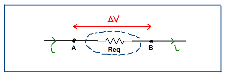
When it comes to circuit solving, we will encounter lot of complex combination of resistors present in the circuit. Finding ‘equivalent’ of such combination of resistors means that, we must be able to replace that whole thing with just a single resistor without changing any of the other parameters (current, potential difference across given points, etc. ) in the circuit.
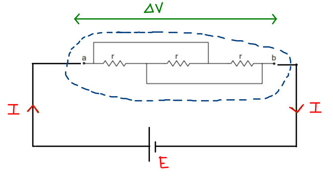
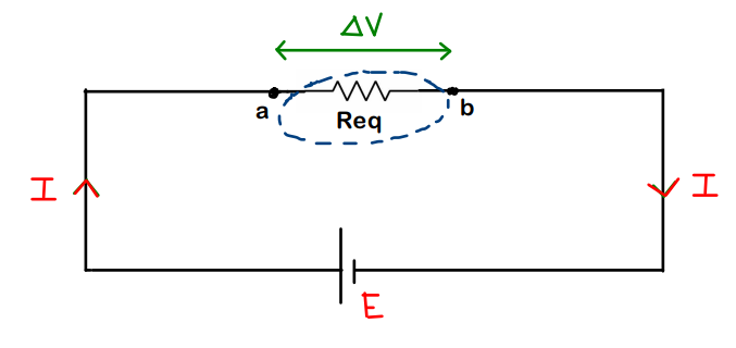
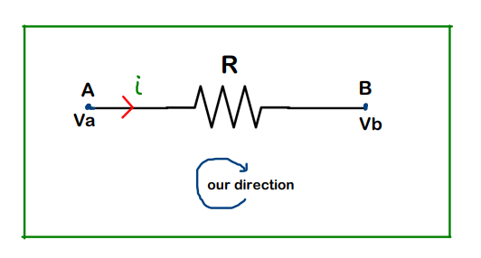
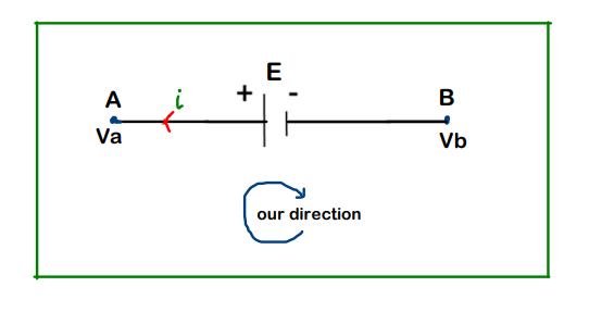
Fig.1 (a) (b)
Note that, in Fig.1 (a) and (b), except the number of resistors, there is no change in other parameters (I remain I, E remains E, delta V remains delta V)
Now, how to actually calculate this value of Req is what we need to study in this article !!
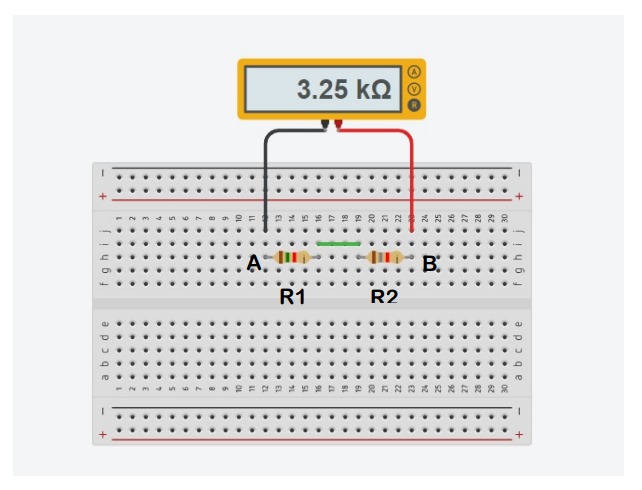
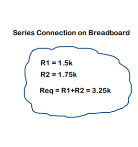
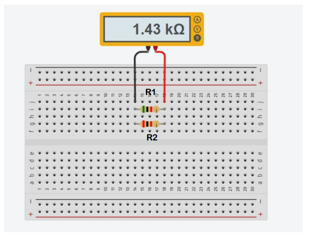
2. Resistors in Series
Resistors are said to be in Series when the current flowing through them is the same. Done !
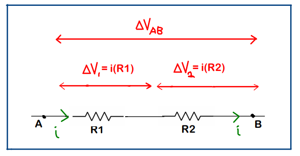
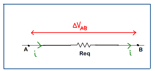
Now, with reference to above figure,

Important Note :
From the above relation, we can infer that, we can use series combination if we need a resistance value greater than the individual resistances (i.e. Req > R1 & also Req > R2)
So, Resistors in Series just add up directly !
3. Resistors in Parallel
Resistors are said to be in parallel, when they have same potential difference across them. Done !


Important Note :
From the above relation, we can infer that we can use parallel combination if we need a resistance value even lower than the individual resistances. (i.e. Req < R1 & also Req < R2)
Breadboard Connections for parallel combination :

4. Example on Series – Parallel
Question -1
Find the equivalent resistance of the given setup across points A and C
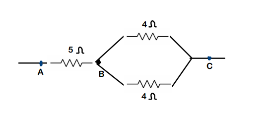
Solution :
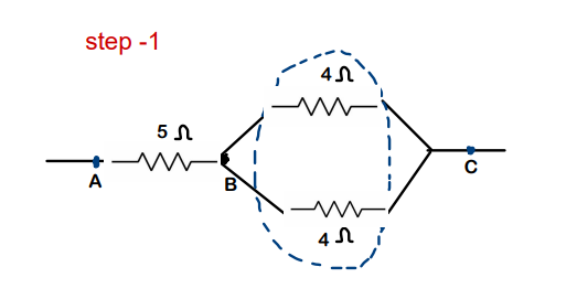
Step – 1 : Both the 4ohms resistors are connected across same points B and C. Hence, Both are in parallel combination. Req for just this combination will be 2 ohm
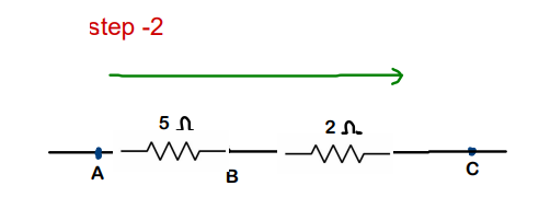
Step-2 : Now, 5ohm and 2 ohm are in series combination. Req of this will be 7ohm
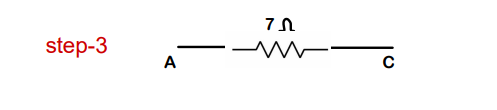
Step-3 : Finally, we have 7 ohm resistor between A and C. This is our final Req between points A and C
Question – 2 :

Solution :
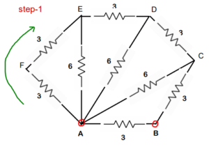
Step 1 : same current passes through AF and FE which makes both the 3 ohm resistors in series. Req for this will be 3+3 = 6 ohms
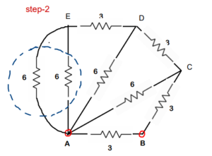
Step 2 : Two 6 ohm resistors are connected across same points A and E which makes them in parallel. Req for this will be 3ohm


Step 3 : again both 3 ohm are in series. Req will be 6 ohm
Step 4 : both 6 ohm are in parallel. Req will be 3 ohm


Step-5 : 3 ohm and 3 ohm are in series. Req of this will be 6 ohm
Step-6: two 6 ohm resistors are in parallel. Req of this will be 3 ohms. Keep on simplifying !!
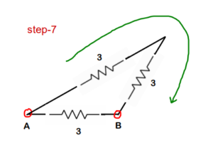
Step-7 : 3 ohm and 3ohm are in series
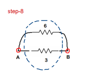
Step-8 : 6 ohm and 3ohm are in parallel. Req of this will be 2ohms.
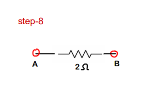
Final Answer : So, the overall equivalent resistance across points A and B is 2ohm
5. Folding Symmetry
(Example will make everything very clear, but keep the below idea in your mind)
- Step 1 : Consider a line passing through the points across which equivalent resistance needs to be found. Let this line be called AB for now.
- Step 2 : See if any folding symmetry exists. Folding needs to be done about the line AB. (By folding symmetry, we mean that there should be an exact overlap once the folding is done).
- Step 3 :Once folding symmetry is confirmed, it implies that all the potentials are also identical at the overlapping points
Let’s take an example to understand this !!
Example :

Solution :
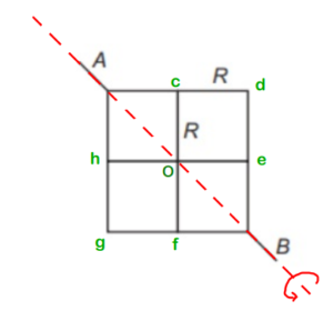

Step-1 : We need to find equivalent resistance across A and B. So we draw line AB first
Step-2 : So we fold one portion of the network about AB and see if it coincides with the portion on other side (Just like a folding of chapati about it’s diameter). And here it does !! – Folding symmetry exists !
Step-3 : Now, since Folding symmetry exists, Vc=Vh (Potential at ‘c’ = Potential at ‘h’) ; Vd = Vg ; Ve = Vf. This implies that the potential difference for the resistor between points ‘A’ and ‘c’ is equal to the potential difference for the resistor between points ‘A’ and ‘h’. This again tells us that, they are in parallel. So, we can just keep one of those resistors but it’s value will become ‘R/2’
(Read it again !)
(We follow similar process for all the remaining resistors & we get the circuit shown below)

Step-4 : Just solve this like a normal Series- Parallel problem


Final Answer : We get the overall equivalent resistance as 3R/2. So option (b) is correct.
6. Mirror Symmetry
- Just check for mirror symmetry about any line (imaginary is also OK) in the circuit
- If any mirror symmetry exists, then the currents in the mirrored branches should also be same. This point is responsible for simplification of the circuit.
Let’s take an example to understand this even better !
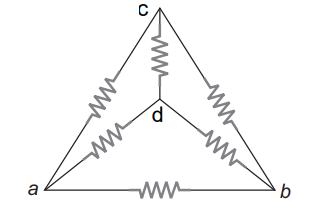
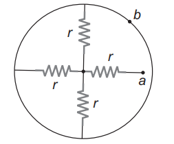
Example :
Find the equivalent resistance of the circuit shown in the figure about points a and b. Each resistor has a resistance ‘r’
Solution :
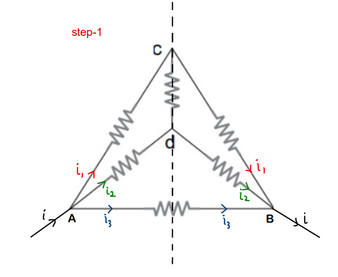
Step-1 :
- Draw the imaginary line about which you find mirror symmetry.
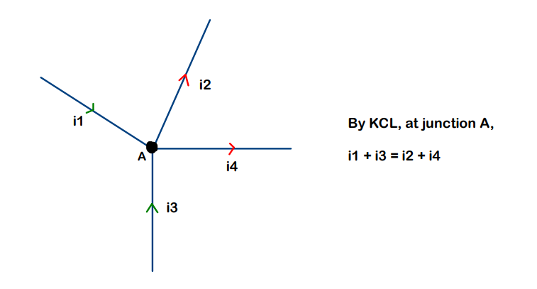
- Consider as if a current ‘i’ enters the whole network through A and gets distributed in branches such that ; i = i1 + i2 + i3
- Because of mirror symmetry, the current in corresponding image branches should also be same and an overall current ‘i’ should come back from B
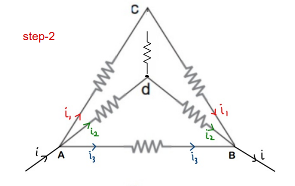
Step-2 :
- ‘i1’ flows in AC and as discussed in step-1, ‘i1’ flows in CB as well
- But applying KCL(junction rule) at C, current ‘i1’ should have been distributed in branches cd and cB. but it doesn’t happen as the whole current ‘i1’ goes into branch cB
- This implies that resistor between points c and d is not actually attached at C even though it just appears to be attached. We can just remove it’s connection
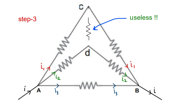
Step-3 :
- Similar thing with i2 !!The current in Ad (i2) should have been divided at ‘d’
- But the whole i2 gets passed on to dB which implies that the resistor is actually not connected to ‘d’ as well (because if it was, then current would have been divided)
Now it is just simple Series-parallel Problem !!


Final Answer : The overall equivalent resistance of the circuit across the points is ‘r/2’
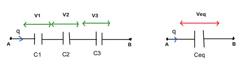
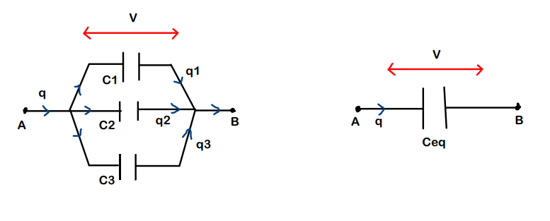
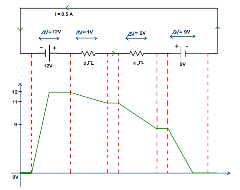
7. Voltage method (Rearrangement)
This method is to be used when we are not directly seeing any kind of symmetry. This method is basically rearrangement of the network in order to get a clearer view to proceed further
Remember :
- Potential remains constant along the plain wires.
- Resistors connected across same potentials are in parallel
(Example will make it more clear)
Procedure :
- Step-1 : Distribute the potentials across the whole circuit. Take care that potential should be defined across both the ends of each resistor. Introduce new variables to denote unknown potentials if needed.
- Step-2 : Number the ends of the resistors
- Step-3 : Write down the potentials separately , keeping the points across which the Req is to be found at the two ends
- Step-4 : Place the resistors between their respective potentials
Let’s take an example to understand this even better !!
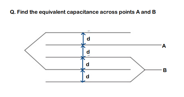
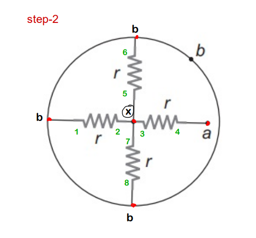
Example : Find equivalent resistance of the given circuit about points ‘a’ and ‘b’
Solution :
Step-1 :
- As we already mentioned, potential along plain wires remains constant.
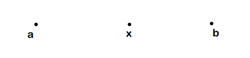
- We are unaware of the potential at the center, so we consider it as ‘x’
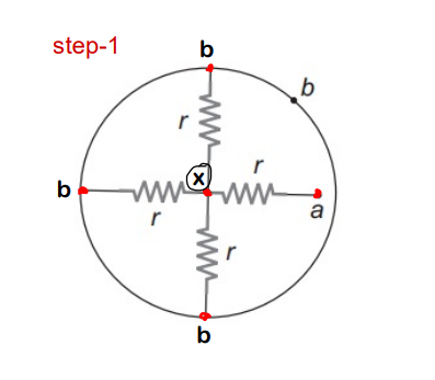
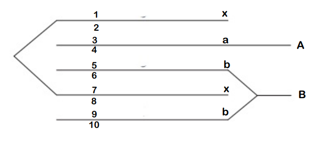
Step-2 :
- Number all the ends of the resistors. (Complete one resistor first and then proceed to next !)
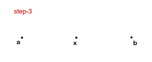
Step-3 :
- Now, separately write down the potentials
- Remember that the points/potentials across which you are calculating equivalent resistance should be kept at the ends
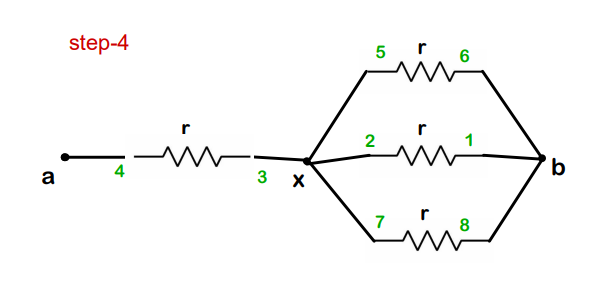
Step-4 :
- Observe and connect the numbers to the respective potentials (a –> 4 ; x–> 3,5,2,7 ; b–>6,1,8 )
- On completing this, you will get a clear view of what the circuit actually was !!
Now, it is just simple Series-Parallel problem !

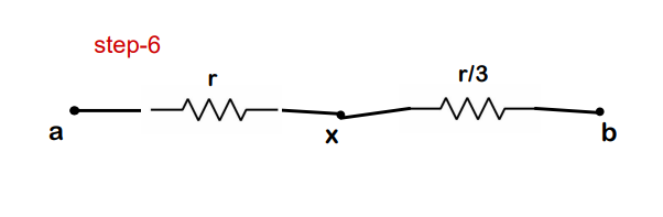
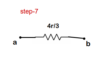
Final Answer : The equivalent resistance of the circuit between a and b is 4r/3
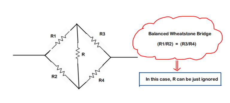
8. Dealing with Wheatstone Bridge
- The below wheatstone configuration is often seen while solving problems based on equivalent resistance.
(I am just adding this so that you don’t feel stuck at any problem just because you were not aware of this !!)
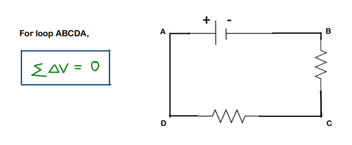
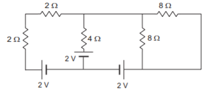
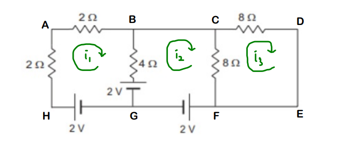
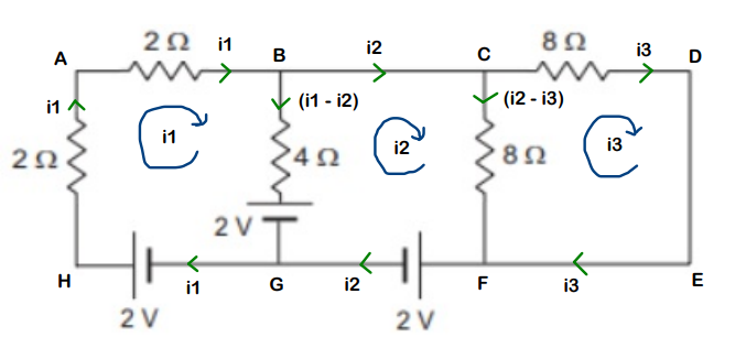
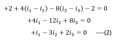
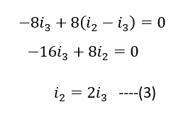
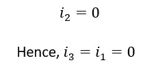
9. Kirchhoff method for Req
When nothing works at all, there is always Kirchhoff method to the rescue !!
10. Assignment & Conclusion :
- So now on completion of both the parts : 1st – Dealing with Resistors and this 2nd- Combining Resistors, We have a good foundation set to understand electric circuits in a much better way.
- This second part was mainly to go into much more depth for understanding circuits based on resistors. later on, we will add capacitors, inductors as well to expand our applications !!
Based on this article, some problems have been shortlisted from popular books, so that you can have a practice kind of thing as well. Solution to this assignment can be asked through email.
For solutions or doubts,
email at : physicsandelectronics079@gmail.com
DOWNLOAD
Combining Resistors - Assignment
All the Best !!
Keep Learning !!