
Use Desktop/Laptop for Best Experience

In this Article, we will try to cover another sensor – Ultrasonic Sensor (HC-SR04).
Topics Covered :
- Working – Basic Theory
- Pinouts & their Contribution
- Interfacing with Arduino – Code Explanation
1. Working – Basic Theory
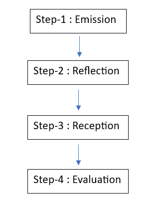
The working of this sensor can be explained in 4 steps :
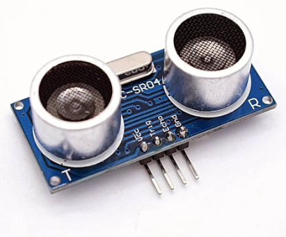
The Ultrasonic Sensor HC-SR04 has a transmitter and a receiver present in the same module
- T –> Transmitter
- R –> Receiver
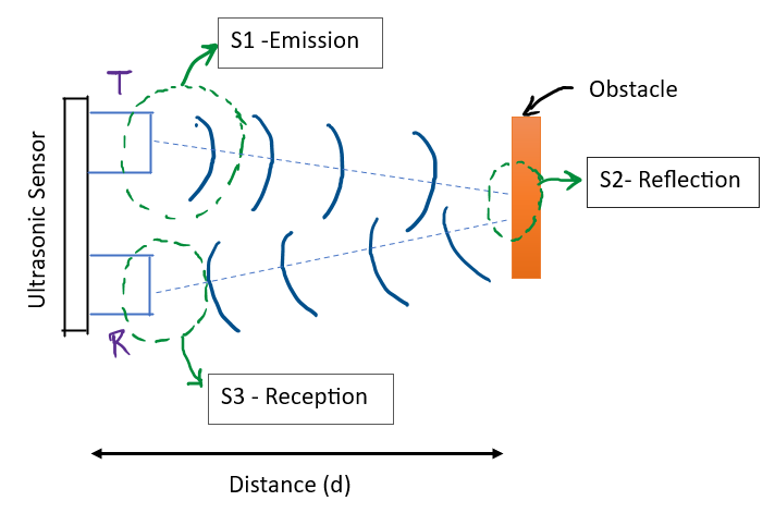
Step-1 : Emission
The Transmitter sends out the ultrasonic sound waves at a high frequency of about 40kHz. By 40kHz, we mean that, the sound waves travels in the medium with a frequency of 40,000 cycles per second
Step-2 : Reflection
The transmitted wave hits the obstacle and gets reflected back
Step-3 : Reception
The reflected wave is then received by the on-board receiver
Step-4: Evaluation
The time required for the sound wave to come back (transmitter to receiver) is calculated. And using this time data and velocity of sound in the medium, we calculate the distance (d) between the sensor and the obstacle.
2. Pinouts & their Contribution
There are 4 pins on the HC-SR04 Ultrasonic Sensor
- VCC
- Trig (Trigger Pin)
- Echo
- GND
VCC Pin :
– The VCC pin is where you provide the +5V power supply
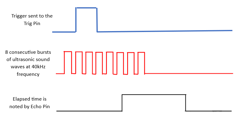
Trig & Echo Pin :
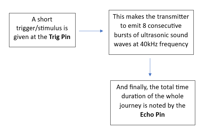
Saying the same thing through some graphs will look like :
GND Pin :
-GND is to as usual connected to the common ground
3. Interfacing with Arduino (Code)
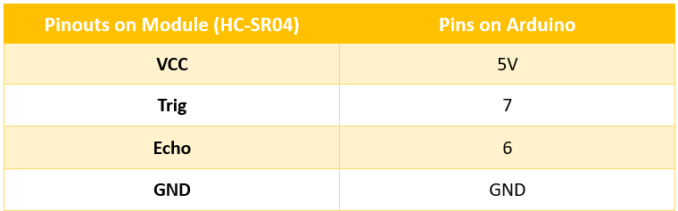
Pin Connections :
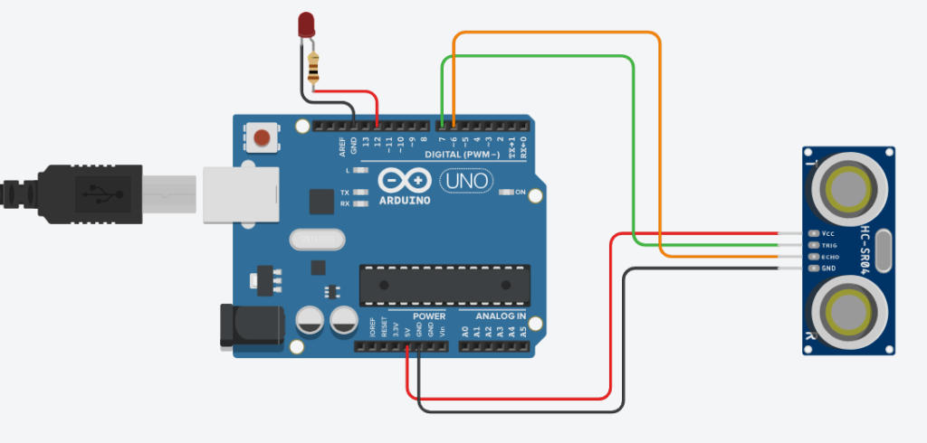
Let’s build a quick mini project to understand the working of this sensor :
- For this, we will be connecting an additional LED in order to get the signal if our code works fine.
TinkerCad Circuit Diagram :
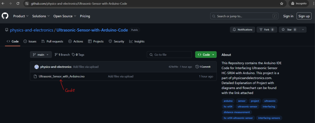
Code :
Code for the Project : GitHub File Link –> Click Here to Access
Explanation :
Code ExplanationAll the Best !
Keep Learning
