Why is Multigrade Engine Oil So Important – Explained

Have you ever thought about how your engine stays protected in both cold winters and hot summers? The answer lies in multigrade engine oil.
Simplifying Everything
Have you ever thought about how your engine stays protected in both cold winters and hot summers? The answer lies in multigrade engine oil.
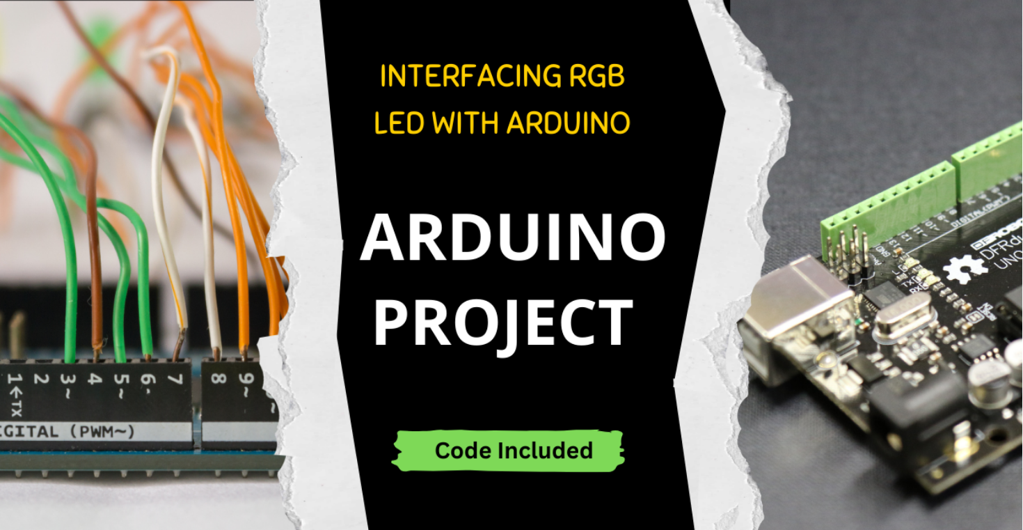
We have already learnt about single colour LEDs. But how about a single LED which can project different colours. Let’s learn how to use this RGB LED in our project
Arrow Indicator Circuit – Interesting Arduino Project for Complete Beginners to start. The Article helps to understand the interfacing of Arduino with basic components like push buttons and LEDs

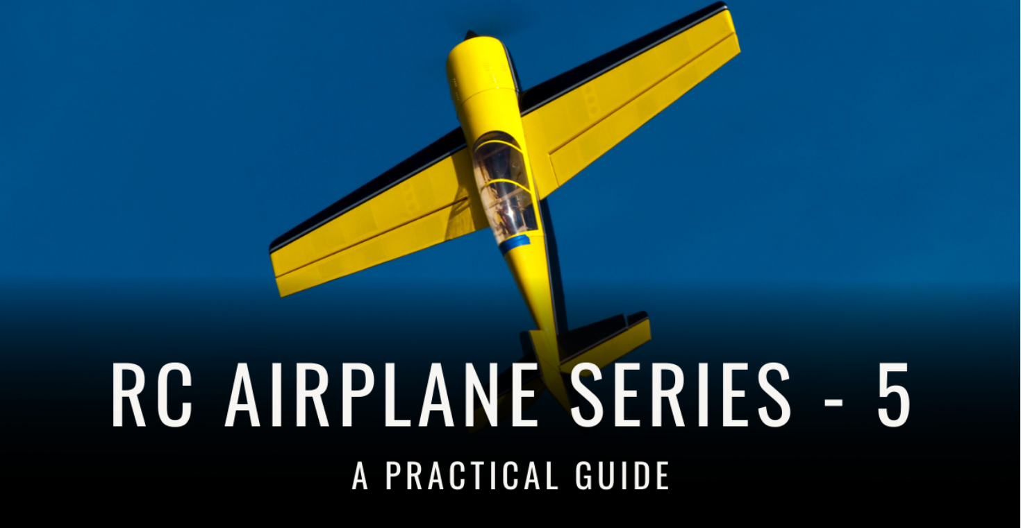
We will be learning about the Electronic speed controller (ESC) and also we will be looking at making circuit connections in our RC plane
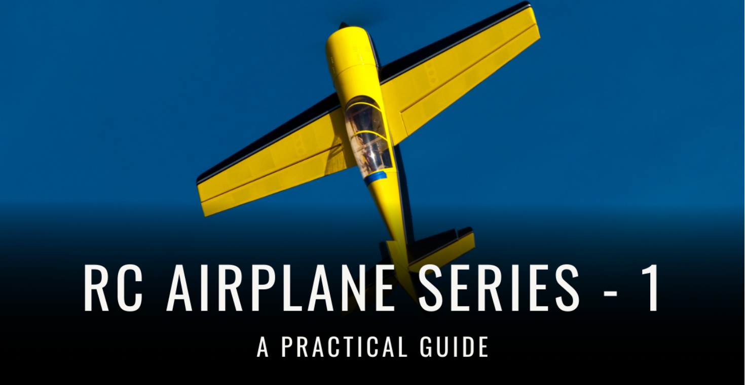
We discuss about the procedure to select the correct LiPo battery for our RC Airplane model. The combo of theory + example makes it easier for reader to understand. Enjoy Learning !!

Learn about the crucial part about the motor + propeller selection. With Theory, an example has been attached for clarity as well. Enjoy learning !!

RC Airplane Series-3: In this article, we learn how to tackle the task of designing the airplane for Beginners. The article covers the methodology required to properly add dimensions to each component for your RC Airplane

GPS, being a very important feature in our phones, is important for us to know: How exactly does it work? This article answers this question in detail without overcomplicating it.

Get the insight about How exactly the Control Surfaces operate and help in controlling the Aircraft. Understand the related working principles of Physics
Learn about the Science behind the Wings of an Aircraft and What are the different concepts & terminologies involved in it