Total Internal Reflection, also known as TIR, is one of the useful phenomenon which has applications in a lot of areas. One such example is of Optical Fiber Cables. In this Article, we will be discussing TIR: What is it? Under what conditions does it happen? What is the difference between ‘normal reflection’ and ‘total internal reflection’?
In simple words, Reflection is nothing but the bouncing back of light into the same medium once it hits a polished hard surface (usually a mirror).
2. How does Total Internal Reflection happen?
When a light travels from one medium to another, it bends. But whether it bends toward the normal or away from the normal depends on the fact from which medium to which medium it is going.
Rarer to Denser – bends towards the normal
Denser to Rarer – bends away from the normal
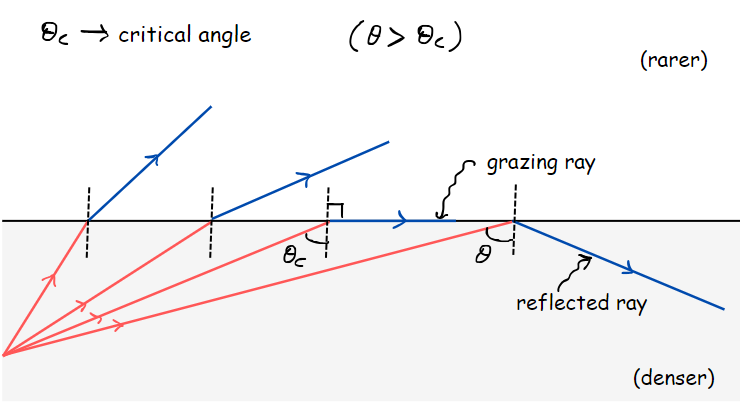
Now, this specific case of Total Internal Reflection (TIR) happens when the light travels from a denser medium to a rarer medium.
From the figure, as we keep increasing the angle of incidence, the angle of refraction also increases until the critical angle is reached.
Critical Angle :
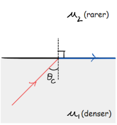
For each medium interface, we have a special angle defined, known as the critical angle. In simple words, it is the angle of incidence at which the refracted ray grazes along the medium-separating interface (the angle of refraction becomes 90 deg).
By Snell’s law,
TIR Condition :
When the angle of incidence goes beyond this critical angle, the ray gets ‘reflected back’ into the ‘same medium’. This phenomenon is called ‘Total Internal Reflection.’
3. Difference between Normal and Total Internal Reflection:
3.1 Normal Reflection:
The intensity of the incident ray is much greater than the intensity of the reflected ray. This is because during normal reflection, a part of the light gets absorbed by the material through which it hits, and some of it gets transmitted further.
3.2 Total Internal Reflection:
In this case, the incident ray intensity is retained 100% by the reflected ray. This is the major difference between Normal Reflection and Total Internal Reflection
A Question from JEE Advanced Previous Year Papers:
Question:
A light ray travelling in a glass medium is incident on the glass-air interface at an angle of incidence. The reflected (R) and transmitted (T) intensities, both as functions of theta, are plotted. The correct sketch is :
Answer : (C) option
At an angle of incidence = 0°: Most of the light (not 100%) is transmitted.
At an angle of incidence > critical angle: 100 % of light is reflected, and hence 0% transmission of light
FAQ section
What is Total Internal Reflection (TIR)?
TIR is the phenomenon in which the incident light travelling from a denser medium to a rarer medium gets reflected back into the denser medium, retaining its full intensity (100%).
What is a grazing ray?
We call a refracted ray a grazing ray when it passes along the interface separating two media.
What is meant by critical angle in TIR?
For each medium interface, we have a special angle defined, known as the critical angle. In simple words, it is the angle of incidence at which the refracted ray grazes along the medium-separating interface (the angle of refraction becomes 90 deg).
Calculation of the charge-to-mass or e/m ratio is of great importance when it comes to the subject of Modern Physics. Understanding the procedure behind this experiment is equivalent to revising the following topics as well :
Ok, so you have a value called e/m ratio! But why is it important to calculate this value? Are there any applications of it?
In simple words, the charge-to-mass ratio of a charge helps us to predict the behaviour of the particle under electric and magnetic fields. This ability to predict the particle’s behaviour enables us to have an idea of adjusting the setup in order to have so-and-so outcomes.
We can see its application in:
Electron Microscopes:
Electron Microscopes are known for their ability to magnify the images to a very high resolution & this is done with the help of a beam of electrons
Knowing the e/m ratio enables the scientists to control the movement of electrons and, as a result, they produce the required resolution of the image
Particle Accelerometers:
These are used to accelerate the charged particles.
By knowing the charge-to-mass ratios, we can actually control the trajectories of the particles.
2. Setup of the Experiment
The Setup mainly consists of the following things :
Filament F
Battery V
Pump
2 parallel plates, across which another battery has been connected
Current-carrying coil wire (not shown in setup)
Screen S
Fig. Setup of the Experiment
Purpose:
Filament F: The filament is inclusive of that battery (not V) shown in the above figure. The flowchart below explains the working of filament
Text Version for the above flowchart (Expand This)
The battery heats the filament
This causes the electrons to get knocked off from the atoms due to the energy given (i.e., thermionic emission)
These electrons form a cloud near the filament once they come out from the atom (since they don’t know what to do next!)
Voltage V : The plate attached to the positive terminal is used as an anode to attract the electron cloud. This is done to make the electrons accelerate. Each electron has different energies when it comes out from atoms. And when they are accelerated due to a potential difference of V, then they all end up having a different set of velocities.
Pump: To create a vacuum inside the tube
The parallel plates kept facing each other + battery setup, is used to create a uniform electric field E in the region between the two plates. Direction will be from the positive plate to the negative plate
Current-carrying coil wire: This is done to set up a steady magnetic field B (going into the plane)
Screen S: Whenever an electron strikes the screen S, it creates a spot on the screen, which helps us to detect and hence analyze the trajectory/path taken by the electron.
Note that: The E and B vectors are perpendicular to each other
3. Procedure
Step-1 :
As discussed, the anode attracts the electron cloud, which makes them accelerate towards the screen S. But well before they reach the screen, the electrons are made to pass through a region R where, for now, only the electric field is applied (B is turned off).
The current setup for Step-1 looks like:
As the electrons pass through ‘Region R‘, they undergo deflection ‘y’ due to the electric field and follow a trajectory as shown (green). We zoom into Region R to get a better understanding of what’s happening.
Zoomed picture of Region R :
We need the expression for deflection ‘y’.
Important: Note that the deflection is going to be measured from the axis
Some of the Projectile comes into the picture now!
Initial velocity in X direction (ux) = v
Initial velocity in Y direction (uy) = 0
Acceleration in X direction (ax) = 0
Acceleration in Y direction (ay) =
Displacement in X direction (Sx) = L
Displacement in X direction (Sy)= y
L = vt
Solving for ‘y’, we get:
This ‘y’ is measured during the experiment
Step-2:
Now, we aim to find the velocity ‘v’ of the electron. Recall that the ‘y’ is the deflection –> BUT Deflection from which path? The answer is ‘the axis’. We need to find the deflection caused in the electron’s trajectory due to the electric field E, because otherwise, in the absence of E, it would just follow the straight path along the axis.
To get the speed (v) of the electrons that go undeflected, we introduce B now in addition to E to make zero deflection. This is equivalent to saying that none of the fields were present in region R
We have to balance the forces (to get zero deflection). Remember, it’s a negative charge.
Force due to electric field:
Force on a moving charge due to a magnetic field:
We then adjust the values of E and B until the magnitudes of the forces are the same. This allows us to build a ‘velocity selector.‘
Velocity Selector :
As discussed in Section 2 of this article, all the electrons come with a different set of velocities. But, for continuing our experiment, we need only the electrons of a specific velocity to be focused on. So, how exactly distinguish those electrons?
We want the electrons to go undeflected. For that,
We can clearly see the relation between E and B with velocity. This means that controlling the values of E and B allows us to select the electrons that have their velocities as E/B. The electrons possessing this specific velocity will go through the region undeflected, and hence we can separate them.
Step-3:
Calculating the e/m ratio with the expressions and equations we got till now :
Substituting v = E/B in the expression of y obtained in step-1, we get:
4. Final Data
Thomson got the value for e/m to be
Today’s accepted e/m value:
We can see a very good match between the two values
Conclusion
This completes our Cathode ray deflection experiment performed by Sir J.J. Thomson for calculating the e/m ratio
The article or the whole experiment procedure itself has a lot of concepts involved in it, which makes it even more important to understand, both as an Experiment as well as a good multi-concept level problem