How to interface RGB Led with Arduino?

Everyone likes colourful LEDs, don’t they? And what if I tell you that we can get all the 3 primary colours (red, green, and blue) in a single LED? Exciting, isn’t it? Here’s where RGB LED comes into the picture. Let’s see how to interface an RGB led with Arduino.

RGB, as we all know, stands for :

  • Red
  • Green
  • Blue

They are one of the primary colours which can be mixed in different proportions to result in various colours.

1. Problem Statement 

  • We need to create a message for our loved ones, but NOT as a direct text message. When I say loved one, it can be your mother, father, sister, or just anyone whom you love and want to express your feelings to! 
  • This has to be done with the RGB LED, Arduino, etc. Frame your own way of conveying your message to the person with the help of the components discussed

*Hint for the Solution: For this project, we will be showing ‘143’ with the help of an RGB LED

2. How does an RGB LED work?

  • As we know, red, Green and Blue are one of the primary colours that can be used to obtain different colours.
  • This is done using different compositions or ratios of the 3 colours during mixing.
  • And how does mixing happen? The answer is that – It just happens under one LED –> This makes the colours get mixed

The best analogy is the painting palette, which we normally use in our drawing classes. Consider having the smaller version of the paints. So, how did you use to obtain different colours? –> By mixing those available colours in different ratios!

Just 6 colours of poster paints
Drawing Palette
  • The given below are some of the shades which you can make with the help of RGB combinations : 
Photo Credits: https://en.wiktionary.org/

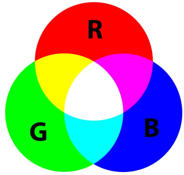
Also, different shades of the colours can be obtained by varying the intensity of the RGB colours

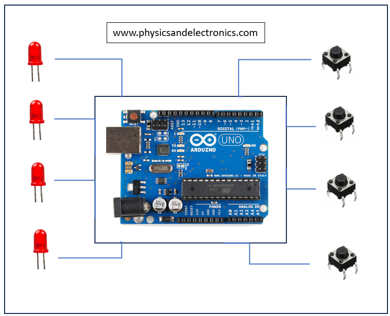
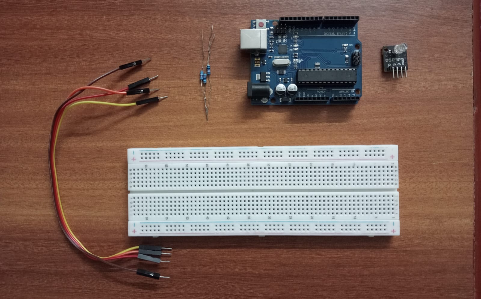
3. Components Required

  • Arduino Uno
  • RGB LED x1
  • Resistors (220 ohms) x3
  • Jumper Wires

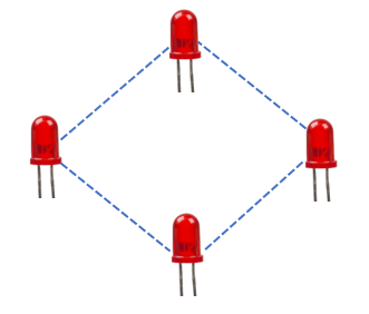
4. Pinouts and Circuit Diagram

The RGB LED has 4 pins –

  • RED
  • BLUE
  • GREEN
  • GND

Always check the pin name associated with the pin. The pin order might change from manufacturer to manufacturer!

Important:

Treat each of the colour pins as a separate LED. Only then can you control each colour on the LED individually.

  • This implies that you will need a separate resistor to protect each of the 3 LEDs – Therefore, we choose three 220 ohms resistors

Schematic Diagram on TinkerCad:

Pin Connections:

5. Explanation and Code

So, as discussed in our Problem Statement, we are going to code our LED such that it somehow conveys the message ‘143’ (A modern way to say “I love you“). This is how it can be done :

Table for understanding the output of the code
  • If you look into the Pinouts Section above, you will notice that the Pins 5, 6, and 9 have a ‘~’ type of symbol adjacent to them on the Arduino Board. This symbol represents that the Pin is a PWM pin.
  • PWM stands for Pulse Width Modulation
  • It’s a kind of additional Superpower which is given to a digital pin to process the data differently if needed. We will be discussing this in detail in upcoming Articles. 
  • For now Let’s take a small example and have an idea about PWM in Layman’s terms.

We know that Digital Pins have only 2 signals – ‘1’ and ‘0’ –> i.e. It’s either ON or it’s OFF, respectively. This case is like a switch that we use to turn ON and turn OFF the fan. 

                                                                                   Fig. For Digital Pins without PWM

BUT Now, PWM is like adding a Regulator besides the switch (it’s just an addition to what we had before). This will allow us to vary and control the speed of the fan as well.

                                                                                   Fig. For Digital Pins with PWM

Code:

The code for the Main Project can be found in the attached GitHub File. The comments will guide you to understand the reasoning for that particular section of code.

You can directly just copy and paste the code given below:

/*
-----------------------------------------------------------
Website: www.physicsandelectronics.com
Refer Article for in-Depth Explanation about this Project & Explore More

Main Project : RGB LED interfacing with Arduino
Instagram : @physics_and_electronics
Youtube Channel : Physics And Electronics - Saurabh Salvi

**Main Code for the Project**
-----------------------------------------------------------
*/

//Declaring pins for each colour on RGB led (All are PWM pins)
int red = 5;      
int green = 6;
int blue = 9;

void setup() {
  // put your setup code here, to run once:
  // All pins are set as OUTPUT
  pinMode(red, OUTPUT);
  pinMode(green, OUTPUT);
  pinMode(blue, OUTPUT);
}

void loop() {
  // put your main code here, to run repeatedly:
//Blink Red Colour once
ledColour(255, 0, 0);  //Keeping only RED colour for 1000ms
delay(1000);
ledColour(0, 0,0);      //Keeping LED off for 800ms (For a pause)
delay(800);

//Blinking the Green Colour 4 times
for(int i=0; i<=3; i++){
  ledColour(0, 255, 0);
  delay(1000);
  ledColour(0, 0,0);
  delay(200);
}
ledColour(0, 0, 0);
delay(800);

//Blinking the Blue Colour 3 times
for(int i=0; i<=2; i++){
  ledColour(0, 0, 255);
  delay(1000);
  ledColour(0, 0,0);
  delay(200);
}

//Keeping White COlour
ledColour(0, 0, 0);
delay(1000);
ledColour(255, 255, 255);
delay(5000);
}

//defining a function for colour selection on RGB Led 
void ledColour(int redVal, int greenVal, int blueVal){

  analogWrite(red, redVal); 
  analogWrite(green, greenVal);
  analogWrite(blue, blueVal);

}

6. Assignment:

You need to design a police siren with flashing alternating red and blue lights. You are free to design your own concept, but please try to stick to these two colors.

  • RGB LED x2
  • Arduino Uno
  • Breadboard
  • Resistors*
  • Wires

*Decide the resistance value yourself. If you want a reference, you can read the related article by clicking HERE

Make the Project in TinkerCad or any other Simulation Software which supports Arduino

For Submission/Doubts: You can send me an email at: connect@physicsandelectronics.com


Conclusion:

So, through this Mini Arduino Project-2, we learnt to interface an RGB LED with Arduino and also learnt some basic working of the same. As discussed, we will be looking into PWM signals in a lot more detail in upcoming articles.

  • Don’t forget to attempt the Assignment Problem. It will allow you to apply the knowledge you gained in the article (Information + Arduino Code) 

Keep Learning!

Arrow Indicator Circuit – Arduino Project


This project mainly aims to cover a part of the basics regarding Arduino IDE and Interfacing of Arduino with other components. Let’s get straight into building this project!

This Arduino project will help you get a clear understanding of the complete methodology to be carried out in order to deal with any project based on this microcontroller.

1. Description of the Project

Fig.1 Arrow Keypad
Fig.2 LED pattern that would appear when the corresponding button is pressed

2. Components Needed for this Arduino Project

  • Arduino Uno
  • Breadboard
  • 4 Red LEDs 
  • 4 Push Buttons
  • 4 Resistors  (220 ohms)
  • Jumper Wires

Reference Article Alert!

How to check the resistance value of your resistor? – Refer to this Article: Dealing with Resistors


3. Understanding and Procedure

3.1 Understanding

Note that there are no connections among the LEDs. 

  • Each LED is separately connected to the Arduino
  • Similarly, each push button is also connected separately to the Arduino Board
  • But the connection between the two (LED and pushbuttons) is done through Arduino. That’s the job of a Microcontroller –> ‘To connect the things as instructed in code.’
Fig. Each LED and each pushbutton is connected separately

We will see how to connect each component with Arduino

3.1.1 Single LED Connections:

  • The adjacent circuit diagram shows the connections that are to be made to control the LED with the help of Arduino
  • The diagram has been prepared with the help of TinkerCad (Simulation Software)

Code for the Blinking of LED can be found below.

/*
-----------------------------------------------------------
Website: www.physicsandelectronics.com


Main Project : Arrow Indicator Circuit - Arduino Project

Sub-Code : Blinking of LED
Objective : To understand the controlling of LED with Arduino

-----------------------------------------------------------
*/


int led = 3; //Assigning pin number 3 for LED

void setup()
{
  pinMode(led, OUTPUT); //LED will be acting as OUTPUT
}

void loop()
{
  //Code to blink LED
  
  digitalWrite(led, HIGH); //Turning ON led 
  delay(2000);			   //Keeping it ON for 2 seconds
  digitalWrite(led, LOW);  //Turning OFF led 
  delay(2000);			   //Keeping it OFF for 2 seconds
}

3.1.2 Single Push Button Connections:

  • The pushbutton serves as an INPUT for most of the time.
  • It gives a value of 0 or LOW when not pressed and gives a value of 1 or HIGH when pressed.
  • There is another way to connect a pushbutton, i.e., by adding a Pull-up Resistor.  

Code for understanding single push button connections is given below. You can directly copy and paste it into your Arduino IDE

/*
-----------------------------------------------------------
Website: www.physicsandelectronics.com


Main Project : Arrow Indicator Circuit - Arduino Project

Sub-Code : Interfacing of Push Button with Arduino
Objective : To know when is the button pressed and when it is not 

-----------------------------------------------------------
*/

int button =7;
int buttonState;

void setup() {
  // put your setup code here, to run once:
pinMode(button, INPUT); //keeping button as INPUT
Serial.begin(9600); // Because we need Serial Monitor
}

void loop() {
  // put your main code here, to run repeatedly:
buttonState = digitalRead(button); // buttonState stores 1 if button is pressed and 0 if not pressed
Serial.println(buttonState);  //Shows the state of button on Serial monitor
}

3.1.3 LED + Push Button:

  • Now that we have learnt to interface the button and LED separately, it’s time to interface them with Arduino at once.
  • Check the code. The comments will guide you to understand the idea behind each line

Code for the ‘controlling LED with Push Button’ is given below. You can directly copy and paste it into your Arduino IDE

/*
-----------------------------------------------------------
Website: www.physicsandelectronics.com


Main Project : Arrow Indicator Circuit - Arduino Project

Sub-Code : Controlling LED with Push Button
Objective : To control LED by Push Button through Arduino 

-----------------------------------------------------------
*/


int led = 8; //Assigning pin number 8 for LED
int pushButton = 7; //Assigning pin number 7 for push button
int buttonState ; //this variable will help us to know whether button is pressed or not

void setup()
{
  pinMode(led, OUTPUT); //LED will be acting as OUTPUT
  pinMode(pushButton, INPUT); //Push Button will act as input
}

void loop()
{
  //Code to control LED with Push Button
  
  
  buttonState = digitalRead(pushButton); //Read the value you are getting from push Button
  
  if(buttonState == 1){ //if button has been pressed
  
    digitalWrite(led, HIGH); // turn the LED ON
  }
  else{
  	digitalWrite(led, LOW); // keep the LED OFF
  }
 }

3.2 Procedure

After Being Comfortable with the above three mini-projects, the main project is very easy to do, as we have done the same thing, but now, it has to be done multiple times.

Step-1:

We need the LED matrix type setup to be in a square shape (diamond shape). So accordingly, we arranged to set up the LEDs and corresponding resistors to protect those LEDs

Reference Article:

How to choose the correct Resistor for a specific coloured LED? – Refer to the Article: Dealing with Resistors

You will learn that –> It is safe to use a higher resistance resistor than the required value. So we go for 220 ohms.

Connect the LEDs as learnt in Section 3.1

Step-2:

  • Attach the 4 Push Buttons to the breadboard in a keypad fashion. 
  • The connections of each button have to be done with Arduino as explained in Section 3.2

Overall Diagram in TinkerCad can be shown as:

The same thing in Reality looks something like:


4. Explanation of Code:

Copy and paste the complete code given below into your Arduino IDE

/*
-----------------------------------------------------------
Website: www.physicsandelectronics.com


Main Project : Arrow Indicator Circuit - Arduino Project

**Main Code for the Project**
-----------------------------------------------------------
*/


int led12 = 2;  //led in row=1 ; column=2
int led21 = 3;	//led in row=2 ; column=1
int led23 = 5;  //led in row=2 ; column=3
int led32 = 6;  //led in row=3 ; column=2

int fwd = 7;	//button for forward 
int right = 8;  //button for right 
int left = 10;  //button for left
int back = 9;   //button for back 

int fwdVal;   //Variable to store the state of fwd button (1 when pressed and 0 when not pressed) 
int rightVal; //Variable to store the state of right button (1 when pressed and 0 when not pressed) 
int leftVal;  //Variable to store the state of left button (1 when pressed and 0 when not pressed) 
int backVal;  //Variable to store the state of back button (1 when pressed and 0 when not pressed) 

void setup()
{
  //keeping leds as OUTPUT
  pinMode(led12, OUTPUT);
  pinMode(led21, OUTPUT);
  pinMode(led23, OUTPUT);
  pinMode(led32, OUTPUT);
  
  //Switches will act as INPUT
  pinMode(fwd, INPUT);
  pinMode(right, INPUT);
  pinMode(left, INPUT);
  pinMode(back, INPUT);

  Serial.begin(9600); //Serial monitor to keep a record of what's happening
}

void loop()
{
  //Checking the situation/state of push buttons
  fwdVal = digitalRead(fwd);
  rightVal = digitalRead(right);
  leftVal = digitalRead(left);
  backVal = digitalRead(back);
    
     Serial.println(fwdVal);

  /*Controlling LEDs in order to represent forward sign if forward button is pressed*/
  
  if(fwdVal == 1){
  	digitalWrite(led12, HIGH);
  	digitalWrite(led21, HIGH);
  	digitalWrite(led23, HIGH);
  	digitalWrite(led32, LOW);
    
  }

 
  /*Controlling LEDs in order to represent backward sign if backward button is pressed*/ 
  
  else if(backVal == 1){
    digitalWrite(led12, LOW);
  	digitalWrite(led21, HIGH);
  	digitalWrite(led23, HIGH);
  	digitalWrite(led32, HIGH);
  }
  
  /*Controlling LEDs in order to represent left sign if left button is pressed*/
  
  else if(leftVal == 1){
    digitalWrite(led12, HIGH);
  	digitalWrite(led21, HIGH);
  	digitalWrite(led23, LOW);
  	digitalWrite(led32, HIGH);
  }
  
  /*Controlling LEDs in order to represent right sign if right button is pressed*/
  
  else if(rightVal == 1){
    digitalWrite(led12, HIGH);
  	digitalWrite(led21, LOW);
  	digitalWrite(led23, HIGH);
  	digitalWrite(led32, HIGH);
  }
  
  //If no button is pressed, then keep all leds OFF
  else{
    digitalWrite(led12, LOW);
  	digitalWrite(led21, LOW);
  	digitalWrite(led23, LOW);
  	digitalWrite(led32, LOW);
  }
  
}
  • We are using some kind of nomenclature here in order to properly keep track of which LED we are talking about or which button we are referring to.

Below is the attached file for Code Explanation. This will exactly give you an idea of the flow that the project code has in it.

Code Explanation - Main Arduino Project

Actual Execution:

When forward key is pressed:

When the left key is pressed:

When the right key is pressed:

When the back key is pressed :

Conclusion:

So, with this, we have learnt to do the basic interfacing of the components with Arduino. There’s still a lot to learn about Arduino. Many sensors can be used for different projects. 

This Article was all about keeping it as basic as possible so that it is more interesting for people/students to read and see

Keep Learning!