For Best Experience, View on Desktop/Laptop !
In this Article, we are going to discuss one of the very important and most discussed method in the chapter of Electric Circuits. It’s used mainly in order to analyze the circuits.
By Analyzing a circuit, we mean :
- Finding current flowing in a branch of circuit
- Finding potential of a point in circuit
- Finding potential difference across the electrical components (resistors, capacitors, inductors, etc.)
There are lot of other techniques as well to simplify and solve the circuits. But When everything fails, this works !!
Topics Covered :
- What are the Kirchhoff’s Laws ? – KCL and KVL
- How to apply it in circuits ?
- Easy – Moderate Examples
- Kirchhoff to find Equivalent Resistance
1. What are Kirchhoff’s Laws ?
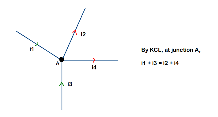
Kirchhoff’s Current Law (KCL) :
Statement : “The sum of all the currents entering a junction is equal to sum of all the currents leaving the junction”
Explanation :
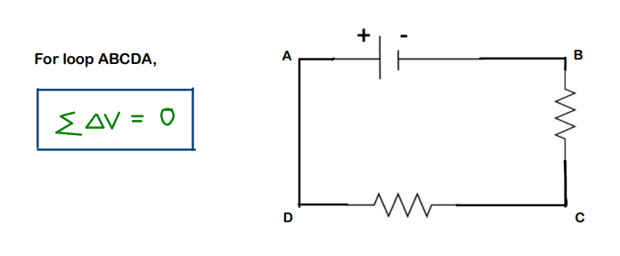
Kirchhoff’s Voltage Law (KVL) :
Statement : The sum of the potential differences across all the circuit elements for a closed loop is always zero
2. How to Apply in Circuits ?
Now, comes the part of where to give plus(+) and where to give minus(-)
For this, just go by the definitions and anything that opposes the definition gets the opposite sign.
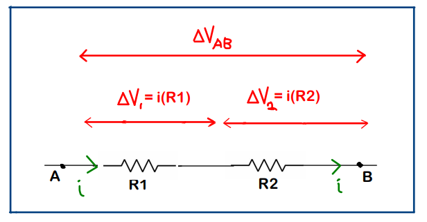
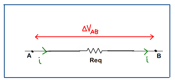
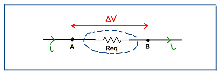
Resistor : It’s a device which causes potential drop and the drop happens in the direction of current. So if we move in the direction of current (through resistor), the voltage has to drop !!
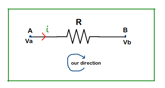
Va is potential at A, while Vb is potential at B
In this case above, the equation can be written as Va – iR = Vb
Battery : Just look at ‘our direction’. If we are moving from positive terminal of battery to neagtive terminal of battery, the voltage is going to decrease (Obvious)
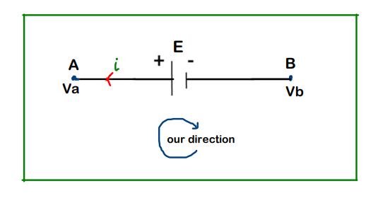
In the above case, the equation can be written as Va – E = Vb
We focus on circuits containing batteries and resistors in this article. Getting a grip on this type of circuits would bring us in a position to easily deal with circuits containing capacitors and inductors as well
3. Easy – Moderate Examples :
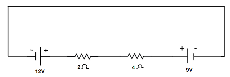
Q.1 Find the current flowing in the loop and also plot a graph which keeps track of the potential across the circuit
Solution :
- We first decide the current direction in the loop ABCDA
- Then, we decide the direction in which we are going to move and according start moving from that point (here A) around the circuit. (Here, we move in A-> B -> C -> D -> A)
- Apply kirchhoff’s law as discussed. (This example will make it a lot clear)
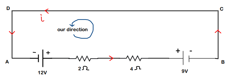
Starting from A ->B,
We encounter 12V battery, As discussed, only consider ‘our direction’ . Here, we move from negative terminal to positive terminal, hence we have potential rise. Hence,
+12
For 2ohm resistor, we are moving in the direction of current, so potential should drop. Hence, equation till now will become
+12 – 2i
For 4ohm resistor, again we are moving in the direction of current, so again potential should drop. Equation is :
+12 – 2i – 4i
For 9V battery, we are moving from positive terminal to negative terminal, so potential drops over here. Hence,
+12 – 2i – 4i – 9
We have completed writing the sum of potential differences across all the elements in circuit (all were present in A -> B). And, according to KVL, this sum should be zero, Therefore,
+12 – 2i – 4i – 9 = 0
i = 0.5 A
The answer is positive which implies that the assumed direction of current is correct.
We draw the graph for keeping track of the voltage rise and drops across the elements (components)
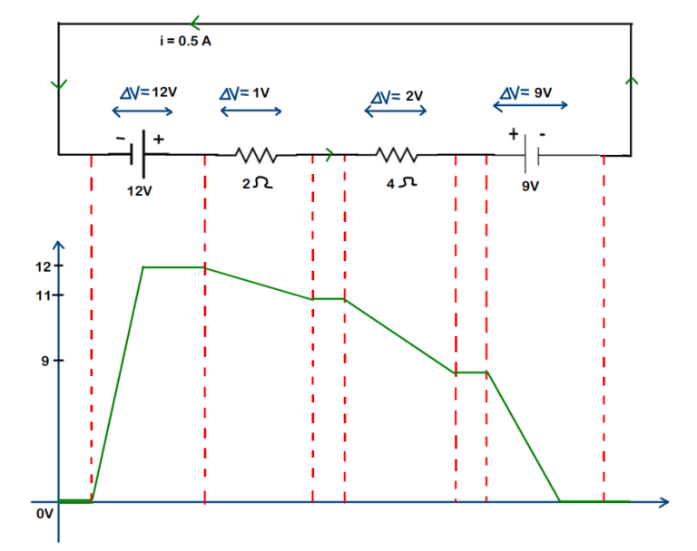
On Y-axis, we have the Voltage (in volts) and we keeping a track of potential wrt the components
– In this, we consider the negative terminal of 12V battery to be at 0V (i.e. our reference).
It’s mandatory to have a point having 0V in any electric circuit. This is because potential at a point can be defined only when the reference has been set
Note : There is no potential drop or rise in wire (it’s constant). Wire can be described as a medium to carry-forward the potential without making any changes in it.
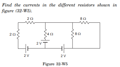
Question-2
Solution :
We give markings first so that it’s easier for us. For each loop, we consider a new current. Let’s do this much first
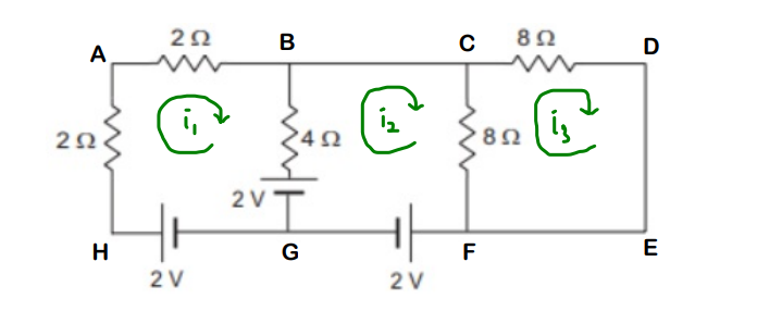
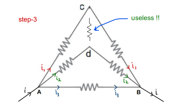
Now, if we see carefully, in the path G-> H -> A -> B, only current i1 will be flowing. But for the branch BG, we have i1 as well as i2 coming into picture since it’s a common branch to loop ABGHA and loop BCFGB.
Hence considering i1 > i2 and also i2 > i3 (you may consider it either way), the current distribution in all the branches becomes,
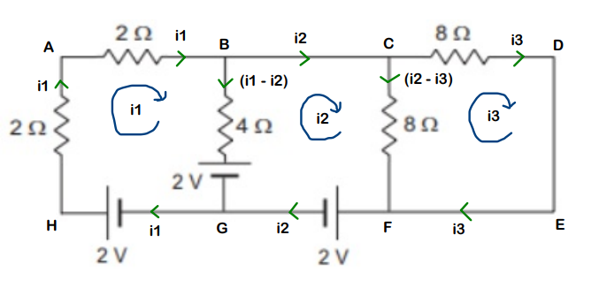
(Observe that KCL is also being followed)
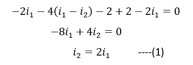
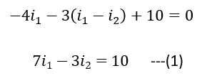
Let’s go loop by loop. First we take loop ABGHA (it means we start from A and end at A)
Eqn is :
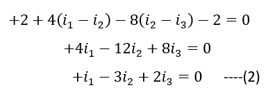
Coming to loop GBCFG, (starting from G)
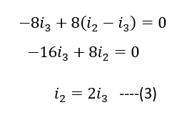
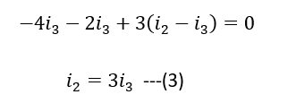
Moving to loop CDEFC, (starting from C)
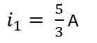
Substitute (1) and (3) in equation (2) for getting value of i2,
We get,
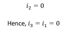
So, we can conclude that there is no current flowing through any of the resistors
Question -3
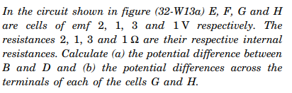
Solution :
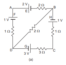
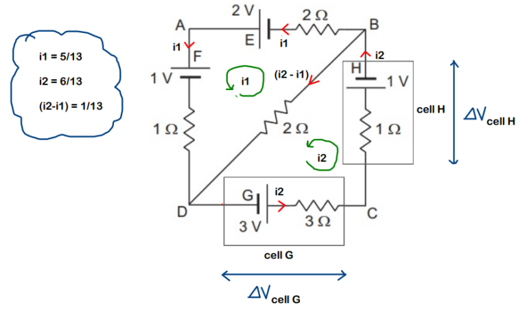
We can clearly see two loops over here. And we consider 2 currents i1 and i2 in each of the loop. It’s completely our choice, whether to consider current in clockwise or in anticlockwise direction. Here, we consider i1 to be clockwise in loop ABDA while i2 to be anticlockwise in loop CDBC.
Refer diagram below.
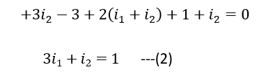
Again same procedure,
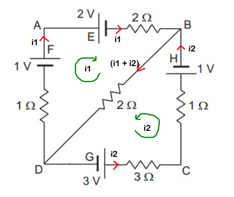
Consider one loop at a time. First, let’s go with ABDA
Coming on to next loop CDBC,
On solving (1) and (2),

Here, i2 is positive while i1 is negative, which implies that the sense of i2 is same as considered (anticlockwise) while for i1, its opposite to what we considered (i.e. in reality, it’s moving in anticlockwise sense)
Actual situation :

For marking the potentials, we need a reference. We choose the negative terminal of 3V (at G) to be at 0V
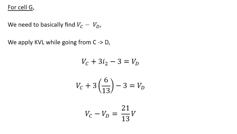
Part – (a)
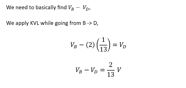
Part – (b)
So, finding the potential difference across cell G is same as finding potential difference between points C and D
while
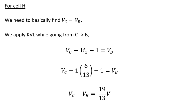
Finding the potential difference across cell H is same as finding potential difference between points C and B
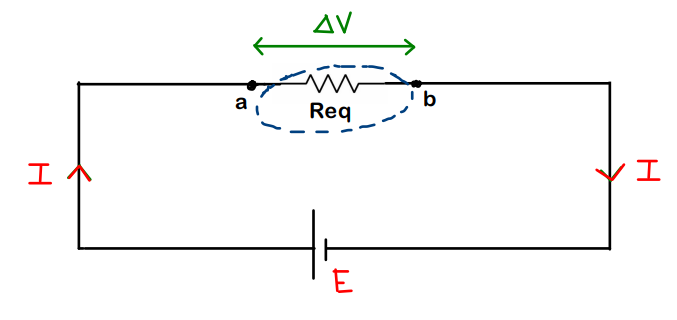
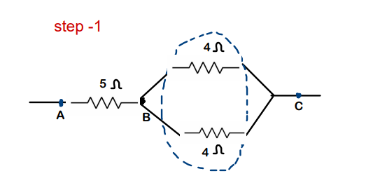
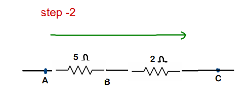
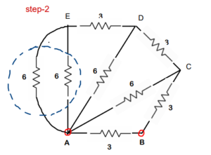
4. Kirchhoff to find Equivalent Resistance
To find equivalent resistance across 2 points given :
- Assume a battery between the 2 points (having voltage of your choice)
- Find the current passing through the battery
- From the relation R = V/I, the value of R is nothing but equivalent resistance
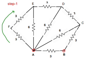
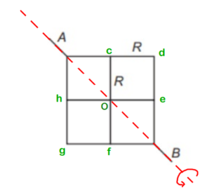
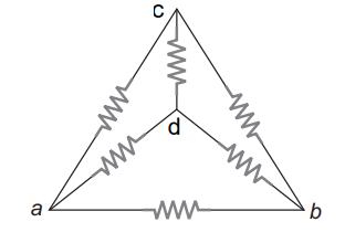
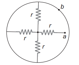
Example :
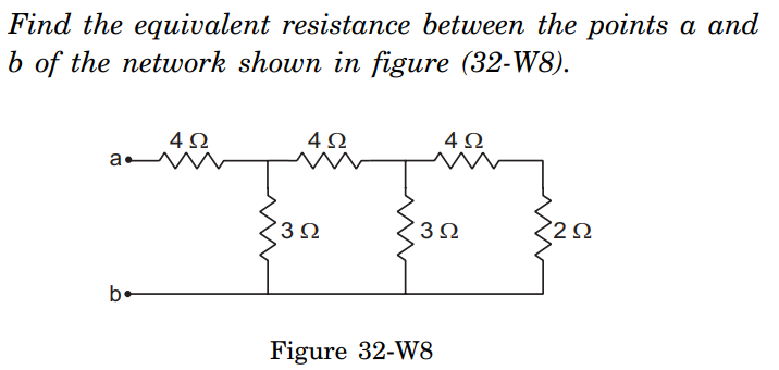
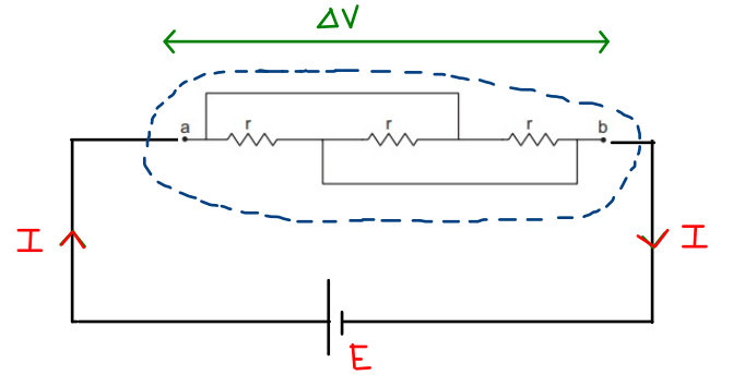
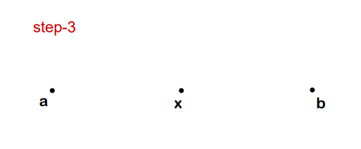
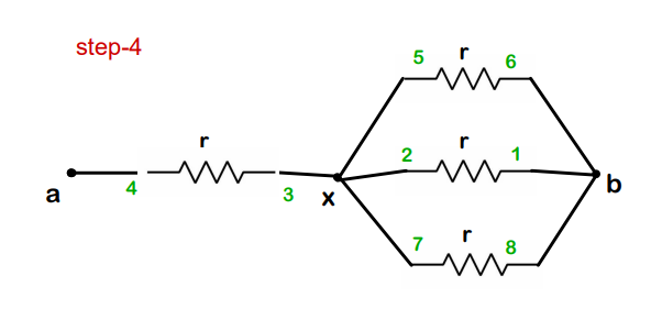
We have 2 points ‘a’ and ‘b’ and we need to find equivalent resistance between these points
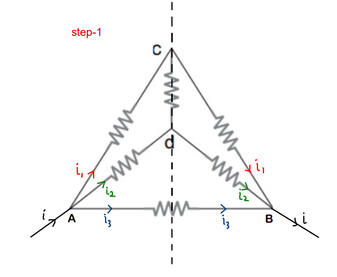
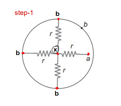
- Step 1 – We consider a battery of 10V between ‘a’ and ‘b’
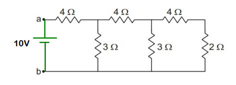
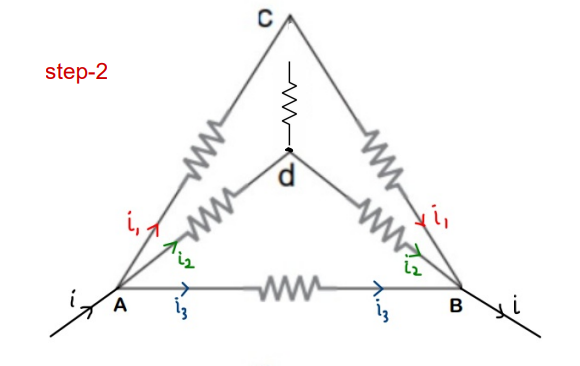
- Step 2 – We need to find current flowing through battery (Here, it’s i1)
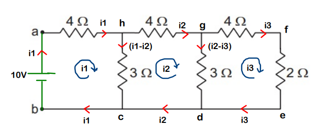
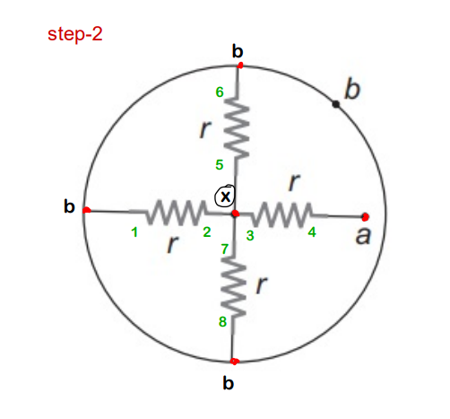
For loop ahcba,
For loop hgdch,

For loop gfedg,
Substitute i3 value from (3) in (2). Solve the new equation with (1) to get the value of i1
We get,
- Step 3 : Use the relation R = V/I. The value of R is nothing but the equivalent resistance between points ‘a’ and ‘b’
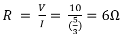
Therefore, the equivalent resistance between ‘a’ and ‘b’ is 6 ohms
Conclusion :
Kirchhoff’s laws can be used in general to analyze all the electric circuits. Though we have even faster techniques to solve the circuits, but incase if we are not able to use any of those, Kirchhoff’s laws will always be there for us !!
This is what makes it important.
Also, apart from it’s importance in just solving problems, it also gives us a very nice understanding on circuit analysis !!
All the Best !!
Keep Learning !!