
In our previous blog on resistors, we learnt what they are and how they are used in circuits generally. In this blog, we will be looking at types of resistors, how the color coding for resistors is done, and what it really tries to tell us. Also, one of the most important parameters that needs to be checked whether the resistor is suitable for our application or not is the Power Rating of the resistor. Without verifying this, you risk your other electronic components, which will be in the vicinity of this specific resistor
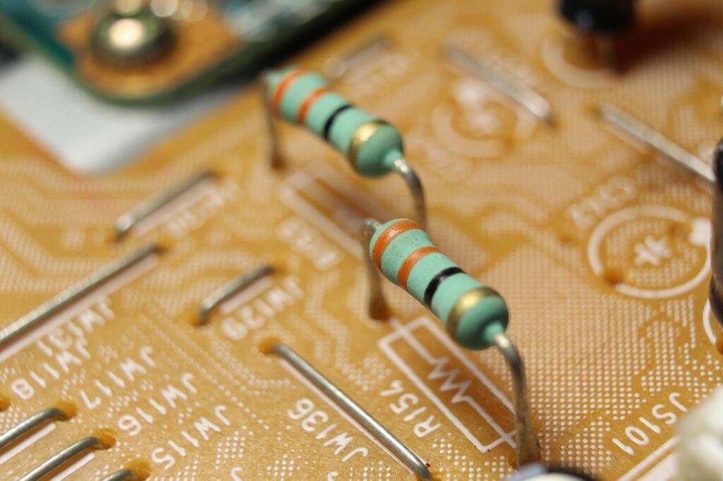
1. Types of Resistors:
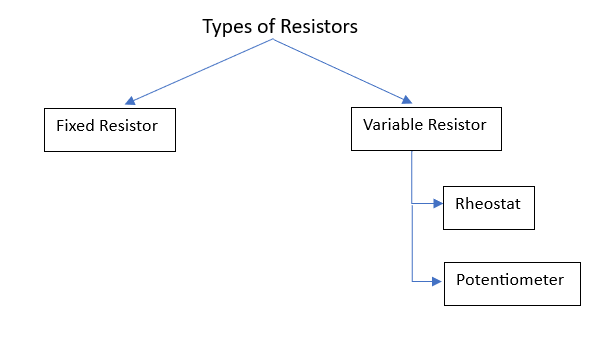
Fixed Value Resistor:
These resistors have their values fixed by the manufacturers themselves. But there can be a slight deflection from the value. We call this deflection ‘tolerance’.

Suppose we have been given a resistor of value ,
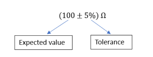
It means the expected value of the resistance is and the Tolerance is 5%
This tells us that the value of the resistor (fixed) can vary from
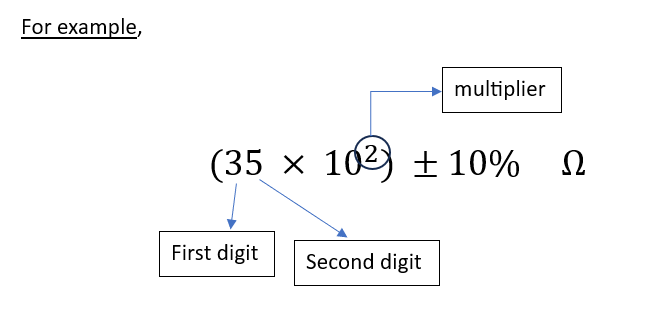
How to calculate the Value of the Resistance? – Color Coding
- The first band gives the first digit
- The second band gives the second digit
- Third band gives the multiplier (the power raised to base 10)
- The fourth band gives you the tolerance value
To clarify even further, we take an example of a fixed resistor having its value of resistance as:
For this, we need to predict the color coding of this resistor. This can be done with the help of the table below, which contains the colors corresponding to their digit, and also tells the tolerance value associated with that color.
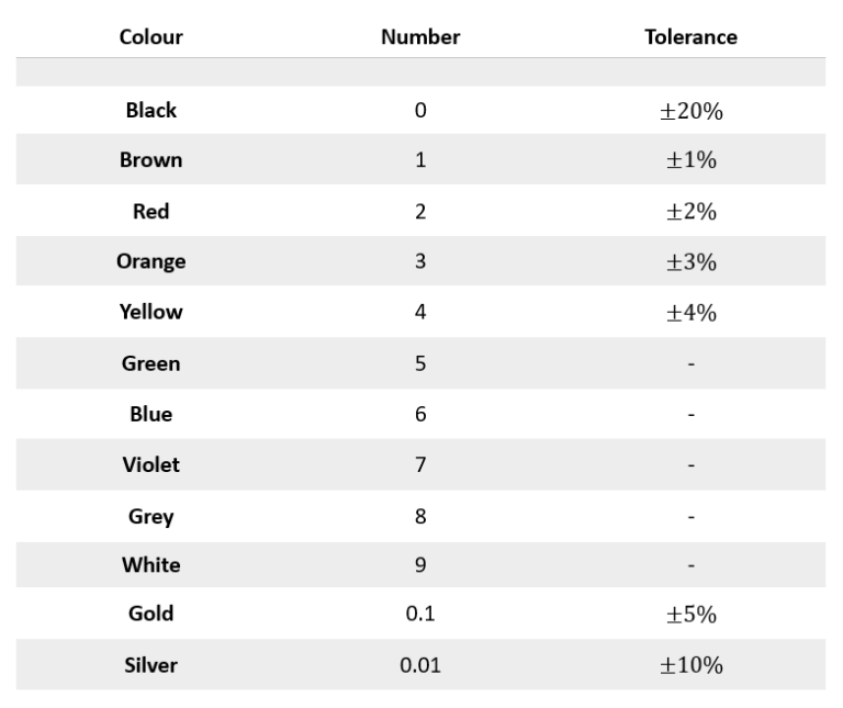
Table for Color Coding of Resistors
| Color | Number/Digit | Tolerance |
| Black | 0 | |
| Brown | 1 | |
| Red | 2 | |
| Orange | 3 | |
| Yellow | 4 | |
| Green | 5 | – |
| Blue | 6 | – |
| Violet | 7 | – |
| Grey | 8 | – |
| White | 9 | – |
| Gold | 0.1 | |
| Silver | 0.01 |
So, for the above example , the color coding will be:
- First band – Orange
- Second band – Green
- Third band – Red
- Fourth band – Silver
Here’s a tool to make your job of choosing the resistor based on color coding even more easy!
Resistor Color Code Calculator
Select the number of bands and their colors to instantly calculate the resistance.
Resistance Value:
Variable Resistors:
- Resistors, whose value can be altered, are known as Variable Resistors. The manufacturer just prints the maximum value that the device can go up to. (For example, if 10K is printed on a potentiometer, it implies that you can adjust its resistance to any value from 0 to 10K ohms).
- The way you can vary the resistance changes from component to component

2. Power Rating of Resistors:
We have learnt about choosing the value of Resistance but whenever current passes through resistors, there is some heat generated as well. Now, we need to take care that this heat doesn’t damage the resistor. For this, we have power ratings assigned to resistors. Power is basically heat generated per second and is measured in Watts (W)
- There is a relation of power with Voltage and Current,
Here, P is the Power (in watts)
V is the potential difference across the resistor (in volts)
I is the current flowing through the resistor (in amperes)
- There are resistors available of 1/8 watt, 1/4 watt, 1/2 watt, 1 watt, etc. The larger the size of the resistor, the higher the power rating it has!
Example:
Suppose the voltage difference across the resistor is going to be 6V, and a current of 20mA is going to pass through it. For the given situation, what should be the suitable power rating of the resistor?
From the above example, we can infer that a resistor of 1/8 W is ‘just’ sufficient. But to ensure even more safety, we can go with a 1/4 W resistor as well.
Conclusion:
Through this article, we tried to learn about resistors and how to perform the basic analysis of circuits involving resistors. According to me, understanding electronics right from the root will be really beneficial.
Learning to deal with Resistors, Capacitors, Inductors, and integrated circuits helps us to build the reasoning behind circuit design.
The Complete Guide on Resistors:
- Part-1: What Is a Resistor & How to Use It in Circuits
- Part-2 (You are here): Types of Resistors, Color Coding & Power Rating
- Part-3: Combining Resistors: Series, Parallel & Equivalent Resistance
- Part-4: How to Solve Resistor Networks – Methods & Examples
Till then, Keep Learning!