
In the last part, we have seen how to solve the cases involving resistors in series and parallel networks. In this blog, we will be looking at some methods to solve complex resistor networks. These methods help in simplifying your resistor networks to such an extent that, after applying them, you can solve them like a normal series-parallel network, as we did in the previous part.
- Other than regular electronic circuits, these methods are essential in solving heat transfer problems where you model the whole system involving different materials (for conduction) and based on the type of heat transfer in terms of their thermal resistance. This helps you model the cooling system and accordingly route the heat to the surroundings.
1. Folding Symmetry
(Example will make everything very clear, but keep the below idea in your mind)
- Step 1: Consider a line passing through the points across which equivalent resistance needs to be found. Let this line be called AB for now.
- Step 2: See if any folding symmetry exists. Folding needs to be done along the line AB. (By folding symmetry, we mean that there should be an exact overlap once the folding is done).
- Step 3: Once folding symmetry is confirmed, it implies that all the potentials are also identical at the overlapping points
Let’s take an example to understand this.
Example:
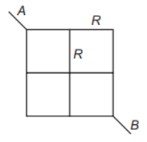
Question : The equivalent resistance between the points A and B is (R is the resistance of each side of the smaller square)
(a) R
(b) 2R
(c) 3R/2
(d) R/2
Solution :
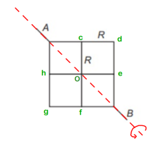
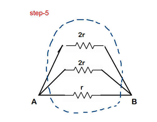
Step-1: We need to find the equivalent resistance across A and B. So we draw line AB first
Step-2: So we fold one portion of the network about AB and see if it coincides with the portion on the other side (Just like a folding of chapati about its diameter). And here it does !! – Folding symmetry exists!
Step-3 : Now, since Folding symmetry exists, Vc=Vh (Potential at ‘c’ = Potential at ‘h’) ; Vd = Vg ; Ve = Vf. This implies that the potential difference for the resistor between points ‘A’ and ‘c’ is equal to the potential difference for the resistor between points ‘A’ and ‘h’. This again tells us that they are in parallel. So, we can just keep one of those resistors, but its value will become ‘R/2’
(Read it again!)
(We follow a similar process for all the remaining resistors & we get the circuit shown below)

Step-4: Just solve this like a normal Series- Parallel problem


Final Answer: We get the overall equivalent resistance as 3R/2. So option (c) is correct.
2. Mirror Symmetry
- Just check for mirror symmetry about any line (imaginary is also OK) in the circuit
- If any mirror symmetry exists, then the currents in the mirrored branches should also be the same. This point is responsible for the simplification of the circuit.
Let’s take an example to understand this even better!
Example :
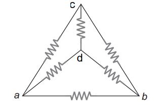
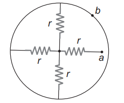
Find the equivalent resistance of the circuit shown in the figure about points a and b. Each resistor has a resistance ‘r.’
Solution :
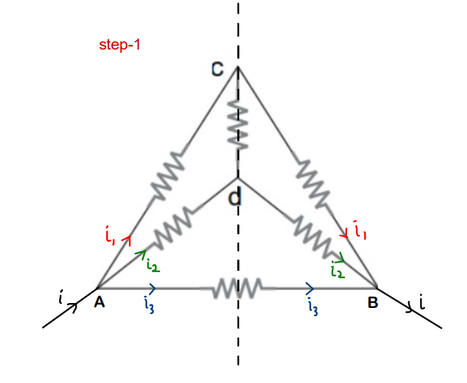
Step-1 :
- Draw the imaginary line about which you find mirror symmetry.
- Consider as if a current ‘i‘ enters the whole network through A and gets distributed in branches such that:
- Because of mirror symmetry, the current in corresponding image branches should also be the same, and an overall current ‘i‘ should come back from B
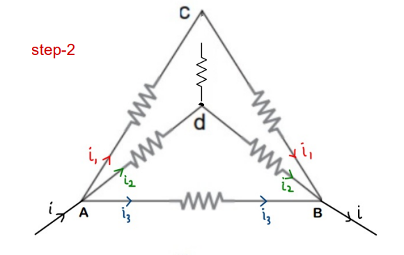
Step-2 :
- ‘i1’ flows in AC and as discussed in step-1, ‘i1‘ flows in CB as well
- But applying KCL(junction rule) at C, current ‘i1‘ should have been distributed in branches Cd and CB. But it doesn’t happen as the whole current ‘i1‘ goes into branch CB
- This implies that the resistor between points c and d is not actually attached at C, even though it just appears to be attached. We can just remove its connection
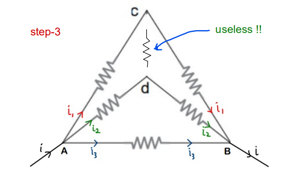
Step-3 :
- Similar thing with i2. The current in branch Ad (i2) should have been divided at ‘d’
- But the whole i2 gets passed on to dB, which implies that the resistor is actually not connected to ‘d’ as well (because if it was, then current would have been divided)
Now it is just a simple Series-parallel Problem
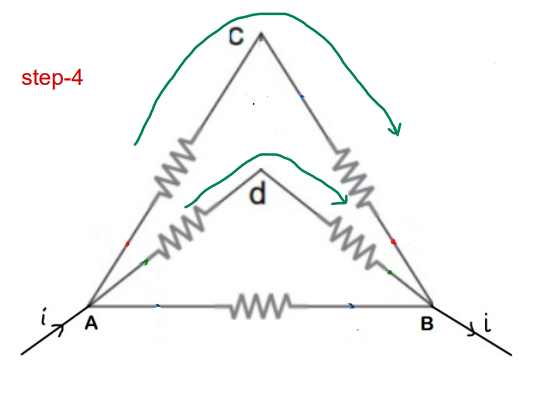

Final Answer: The overall equivalent resistance of the circuit across the points is ‘r/2’
3. Voltage method (Rearrangement)
This method is to be used when we are not directly seeing any kind of symmetry. This method is basically a rearrangement of the network to get a clearer view to proceed further
Remember :
- Potential remains constant along the plain wires.
- Resistors connected across the same potentials are in parallel
(Example will make it clearer)
Procedure :
- Step-1: Distribute the potentials across the whole circuit. Take care that potential should be defined across both ends of each resistor. Introduce new variables to denote unknown potentials if needed.
- Step-2: Number the ends of the resistors
- Step-3: Write down the potentials separately, keeping the points across which the Req is to be found at the two ends
- Step-4: Place the resistors between their respective potentials
Let’s take an example to understand this even better !!
Example: Find the equivalent resistance of the given circuit at points ‘a’ and ‘b’
Solution :
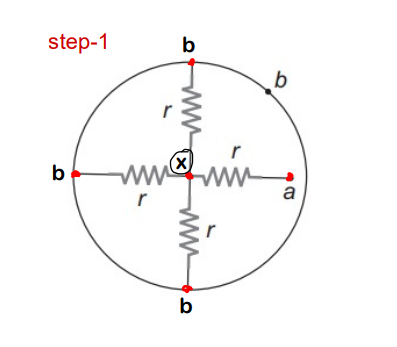
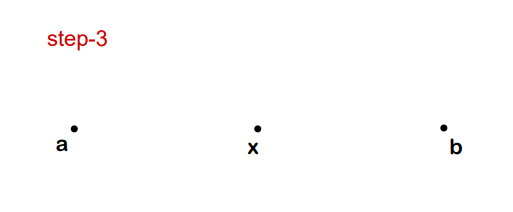
Step-1:
- As we already mentioned, potential along plain wires remains constant.
- We are unaware of the potential at the center, so we consider it as ‘x.’
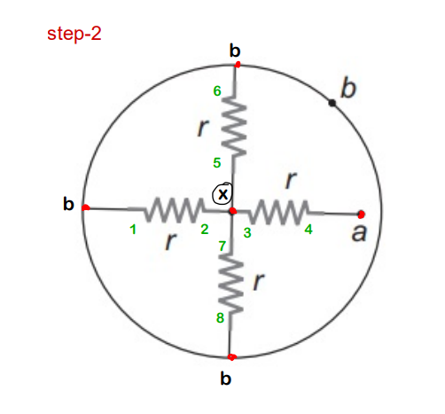
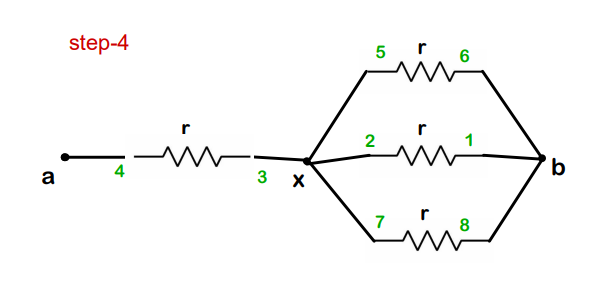
Step-2:
- Number all the ends of the resistors. (Complete one resistor first and then proceed to the next !)
Step-3:
- Now, separately write down the potentials
- Remember that the points/potentials across which you are calculating equivalent resistance should be kept at the ends
Step-4:
- Observe and connect the numbers to the respective potentials (a –> 4; x–> 3,5,2,7; b–>6,1,8 )
- On completing this, you will get a clear view of what the circuit actually was.
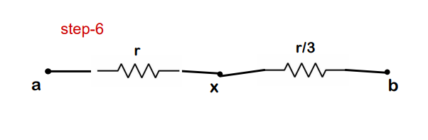
Now, it is just a simple Series-Parallel problem.

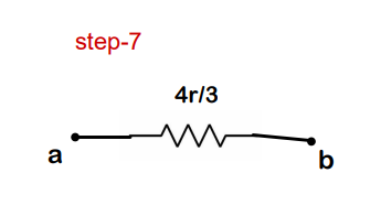
Final Answer: The equivalent resistance of the circuit between a and b is 4r/3
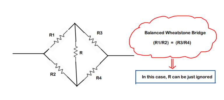
4. How to solve the Wheatstone Bridge?
- The Wheatstone configuration below is often seen while solving problems based on equivalent resistance.
(I am just adding this so that you don’t feel stuck at any problem just because you were not aware of this)
5. Kirchhoff method for solving resistor networks:
When nothing works at all, there is always the Kirchhoff method to the rescue.
- We have already discussed it in the article: Circuit Analysis using Kirchhoff’s Laws
You can solve more problems based on equivalent resistance by visiting this link (MIT Course problems pdf) – Click here
Conclusion:
- So now, on completion of all three parts, we have a good foundation to understand electric circuits in a much better way.
- This third part was mainly to go into much more depth for understanding circuits based on resistors. You can also explore the blogs that I have written on the topic of capacitors because the combination of both opens up the gate to build many more types of circuits.
The Complete Guide on Resistors:
- Part-1: What Is a Resistor & How to Use It in Circuits
- Part 2: Color Coding & Combining Resistors: Series-Parallel Combinations
- Part-3 (You are here): How to Solve Resistor Networks – Methods & Examples
Keep Learning!
