This project of LED Arrow Indicator Circuit mainly aims to cover a part of the basics regarding Arduino IDE and Interfacing of Arduino with other components. Let’s get straight into building this project!
This Arduino project will help you get a clear understanding of the complete methodology to be carried out in order to deal with any project based on this microcontroller.
1. Description of the Project
Problem Statement:
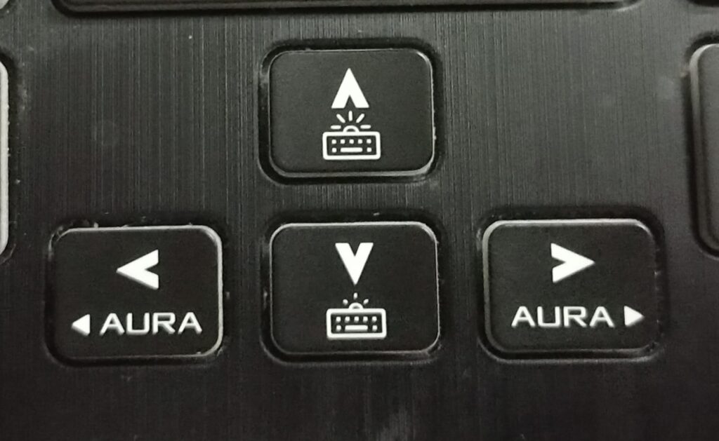
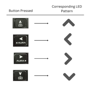
Our main objective for the project is to make an Arrow Keypad-like thing in order to control the LEDs. The LEDs indicate the direction corresponding to the button that we pressed on the keypad
2. Components Needed for this Arduino Project

- Arduino Uno
- Breadboard
- 4 Red LEDs
- 4 Push Buttons
- 4 Resistors (220 ohms)
- Jumper Wires
Reference Article:
How to check the resistance value of your resistor? – Refer to this Article: Color Coding, Combination of Resistors
3. Understanding and Procedure
3.1 Understanding
Note that there are no connections among the LEDs.
- Each LED is separately connected to the Arduino
- Similarly, each push button is also connected separately to the Arduino Board
- But the connection between the two (LED and pushbuttons) is done through Arduino. That’s the job of a Microcontroller –> ‘To connect the things as instructed in code.’
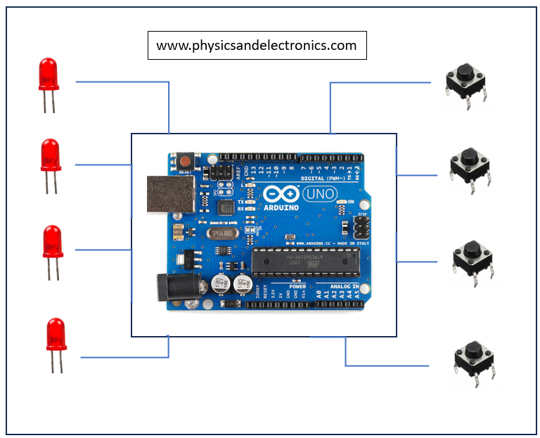
We will see how to connect each component with Arduino
3.1.1 Single LED Connections:
- The adjacent circuit diagram shows the connections that are to be made to control the LED with the help of Arduino
- The diagram has been prepared with the help of TinkerCad (Simulation Software)

Code for the Blinking of LED can be found below.
/*
-----------------------------------------------------------
Website: www.physicsandelectronics.com


Main Project : Arrow Indicator Circuit - Arduino Project

Sub-Code : Blinking of LED
Objective : To understand the controlling of LED with Arduino

-----------------------------------------------------------
*/


int led = 3; //Assigning pin number 3 for LED

void setup()
{
  pinMode(led, OUTPUT); //LED will be acting as OUTPUT
}

void loop()
{
  //Code to blink LED

  digitalWrite(led, HIGH); //Turning ON led
  delay(2000);			   //Keeping it ON for 2 seconds
  digitalWrite(led, LOW);  //Turning OFF led
  delay(2000);			   //Keeping it OFF for 2 seconds
}
3.1.2 Single Push Button Connections:
- The pushbutton serves as an INPUT for most of the time.
- It gives a value of 0 or LOW when not pressed and gives a value of 1 or HIGH when pressed.
- There is another way to connect a pushbutton, i.e., by adding a Pull-up Resistor.

Code for understanding single push button connections is given below. You can directly copy and paste it into your Arduino IDE
/*
-----------------------------------------------------------
Website: www.physicsandelectronics.com


Main Project : Arrow Indicator Circuit - Arduino Project

Sub-Code : Interfacing of Push Button with Arduino
Objective : To know when is the button pressed and when it is not

-----------------------------------------------------------
*/

int button =7;
int buttonState;

void setup() {
  // put your setup code here, to run once:
pinMode(button, INPUT); //keeping button as INPUT
Serial.begin(9600); // Because we need Serial Monitor
}

void loop() {
  // put your main code here, to run repeatedly:
buttonState = digitalRead(button); // buttonState stores 1 if button is pressed and 0 if not pressed
Serial.println(buttonState);  //Shows the state of button on Serial monitor
}
3.1.3 LED + Push Button:
- Now that we have learnt to interface the button and LED separately, it’s time to interface them with Arduino at once.
- Check the code. The comments will guide you to understand the idea behind each line

Code for the ‘controlling LED with Push Button’ is given below. You can directly copy and paste it into your Arduino IDE
/*
-----------------------------------------------------------
Website: www.physicsandelectronics.com


Main Project : Arrow Indicator Circuit - Arduino Project

Sub-Code : Controlling LED with Push Button
Objective : To control LED by Push Button through Arduino

-----------------------------------------------------------
*/


int led = 8; //Assigning pin number 8 for LED
int pushButton = 7; //Assigning pin number 7 for push button
int buttonState ; //this variable will help us to know whether button is pressed or not

void setup()
{
  pinMode(led, OUTPUT); //LED will be acting as OUTPUT
  pinMode(pushButton, INPUT); //Push Button will act as input
}

void loop()
{
  //Code to control LED with Push Button


  buttonState = digitalRead(pushButton); //Read the value you are getting from push Button

  if(buttonState == 1){ //if button has been pressed

    digitalWrite(led, HIGH); // turn the LED ON
  }
  else{
  	digitalWrite(led, LOW); // keep the LED OFF
  }
 }
3.2 Procedure
After Being Comfortable with the above three mini-projects, the main project is very easy to do, as we have done the same thing, but now, it has to be done multiple times.
Step-1:
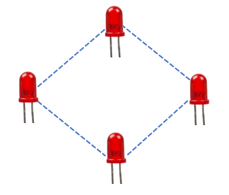
We need the LED matrix type setup to be in a square shape (diamond shape). So accordingly, we arranged to set up the LEDs and corresponding resistors to protect those LEDs
Reference Article:
How to choose the correct Resistor for a specific colored LED? – Click Here
You will learn that -> It is safe to use a higher resistance resistor than the required value. So we go for 220
Connect the LEDs as learnt already
Step-2:

- Attach the 4 Push Buttons to the breadboard in a keypad fashion.
- The connections of each button have to be done with Arduino, as explained earlier
Overall Diagram in Tinkercad can be shown as:

The same thing in Reality looks something like:

4. Explanation of Code:
Copy and paste the complete code given below into your Arduino IDE
/*
-----------------------------------------------------------
Website: www.physicsandelectronics.com


Main Project : Arrow Indicator Circuit - Arduino Project

**Main Code for the Project**
-----------------------------------------------------------
*/


int led12 = 2;  //led in row=1 ; column=2
int led21 = 3;	//led in row=2 ; column=1
int led23 = 5;  //led in row=2 ; column=3
int led32 = 6;  //led in row=3 ; column=2

int fwd = 7;	//button for forward
int right = 8;  //button for right
int left = 10;  //button for left
int back = 9;   //button for back

int fwdVal;   //Variable to store the state of fwd button (1 when pressed and 0 when not pressed)
int rightVal; //Variable to store the state of right button (1 when pressed and 0 when not pressed)
int leftVal;  //Variable to store the state of left button (1 when pressed and 0 when not pressed)
int backVal;  //Variable to store the state of back button (1 when pressed and 0 when not pressed)

void setup()
{
  //keeping leds as OUTPUT
  pinMode(led12, OUTPUT);
  pinMode(led21, OUTPUT);
  pinMode(led23, OUTPUT);
  pinMode(led32, OUTPUT);

  //Switches will act as INPUT
  pinMode(fwd, INPUT);
  pinMode(right, INPUT);
  pinMode(left, INPUT);
  pinMode(back, INPUT);

  Serial.begin(9600); //Serial monitor to keep a record of what's happening
}

void loop()
{
  //Checking the situation/state of push buttons
  fwdVal = digitalRead(fwd);
  rightVal = digitalRead(right);
  leftVal = digitalRead(left);
  backVal = digitalRead(back);

     Serial.println(fwdVal);

  /*Controlling LEDs in order to represent forward sign if forward button is pressed*/

  if(fwdVal == 1){
  	digitalWrite(led12, HIGH);
  	digitalWrite(led21, HIGH);
  	digitalWrite(led23, HIGH);
  	digitalWrite(led32, LOW);

  }


  /*Controlling LEDs in order to represent backward sign if backward button is pressed*/

  else if(backVal == 1){
    digitalWrite(led12, LOW);
  	digitalWrite(led21, HIGH);
  	digitalWrite(led23, HIGH);
  	digitalWrite(led32, HIGH);
  }

  /*Controlling LEDs in order to represent left sign if left button is pressed*/

  else if(leftVal == 1){
    digitalWrite(led12, HIGH);
  	digitalWrite(led21, HIGH);
  	digitalWrite(led23, LOW);
  	digitalWrite(led32, HIGH);
  }

  /*Controlling LEDs in order to represent right sign if right button is pressed*/

  else if(rightVal == 1){
    digitalWrite(led12, HIGH);
  	digitalWrite(led21, LOW);
  	digitalWrite(led23, HIGH);
  	digitalWrite(led32, HIGH);
  }

  //If no button is pressed, then keep all leds OFF
  else{
    digitalWrite(led12, LOW);
  	digitalWrite(led21, LOW);
  	digitalWrite(led23, LOW);
  	digitalWrite(led32, LOW);
  }

}- We are using some kind of nomenclature here in order to properly keep track of which LED we are talking about or which button we are referring to.


Below is the attached file for Code Explanation. This will exactly give you an idea of the flow that the project code has in it.
flow-impActual Execution:
When forward key is pressed:

When the left key is pressed:

When the right key is pressed:

When the back key is pressed :

Conclusion:
So, with this, we have learnt to do the basic interfacing of the components with Arduino. There’s still a lot to learn about Arduino. Many sensors can be used for different projects.
This Article was all about keeping it as basic as possible so that it is more interesting for people/students to read and see.
Keep Learning!
