
Consider 2 situations. For the first case, suppose you are running freely on an open ground; for the second case, consider yourself running at the Mumbai local station (that too during peak working hours). Immediately, you will notice that you can’t run that freely in the second case. What’s the reason?


Resistance. The crowd at the railway station acts like an obstruction for you while you try to run. A similar obstruction is felt by those tiny electrons while moving from the conductor. We term the difficulty that electrons face in flowing due to the object’s opposition’Resistance.‘
1. What factors affect Resistance?

1.1 Material:
- Materials that are good conductors allow easy flow of electrons through them since the nucleus in the atoms doesn’t influence the valence electrons much, due to which they get easily detached from the atoms and contribute to the current. (Imagine atoms of conductors as not-so-strict parents).
- On the other hand, we have insulators that don’t allow electrons to flow freely. This is due to the very strong influence of the nucleus on the valence electrons, and because of this, the electrons are tightly bound to atoms. (Imagine atoms of insulators as very strict parents)


We refer to this property of material as ‘Resistivity‘.It is basically a characteristic of the material. So, conductors have lower resistivity as compared to insulators since they offer less resistance to electron flow for a given volume.
1.2 Cross-sectional Area:
- From our daily life experiences, we know that driving on a broad highway feels much freer than driving on a narrow road. Because of this, the first thing we try to do on the highway is to speed up our vehicle. On a similar basis, when the area of cross-section of a wire is greater, the resistance is lower, hence making electron flow easier.

1.3 Length and Area of Cross-Section:
- The longer the length of the wire/object, implies that more atoms/molecules will interact with the electrons, hence increasing the obstruction. So, Resistance is high in this case
Taking into account all the above 3 factors (Material, Cross-sectional Area, and length), we can compress it into a formula as:
- R is the resistance
- is the Resistivity – a property of the material
- A is the area of the cross-section
- l is the length

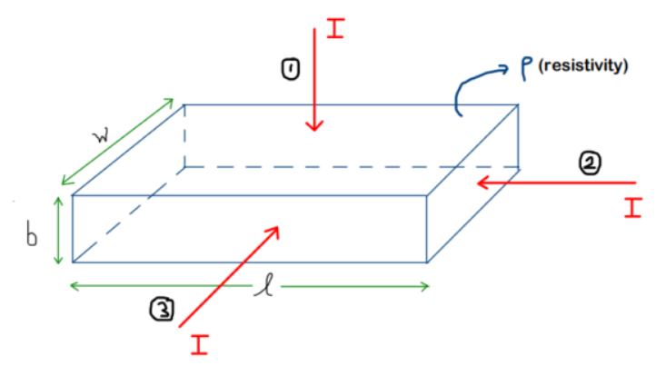
Question: Given below is the cross-section of a wire, and the direction of current is shown for each case. Write down the expression for resistance R for each of the cases (case-1,2,3)
Solution :
Important to Note : In the formula of R, rho is the resistivity, L is the length (along the current direction), and A is the area of cross-section (current passes through this section of area while passing)
CASE-1:

Final Answer for the case-1:
CASE-2:

Final Answer for Case-2:
CASE-3 :

Final Answer for Case-3:
1.4 Temperature:
Usually, in normal cases, as the temperature increases, the resistance is seen to increase. There is also a relationship between the resistance and the temperature.
- is the original/initial resistance
- is the temperature coefficient of resistance
- is the temperature difference
2. Use of Resistors in Circuits:
Ok, so now coming to the main portion: what is the actual use of a resistor in any electronic circuit !? Answering this question, there are 2 main uses of a resistor :
- Limiting the current
- Controlling the voltage
2.1 Limiting the current:
Resistors are commonly used to make sure that only the current required by the device goes into it, nothing more! Getting excess current than required can damage the devices very badly (i.e., it might even burn them off This happens mostly with sensitive elements like LEDs, ICs, transistors, etc.)
Let’s consider a problem.
Suppose that you need to make a red LED glow with the help of a 9V battery. So, shall we just directly connect the 9V battery to the LED? What happens if we do that?


Basically, if we directly connect the battery to the LED, there is a lot of current flowing through the LED, which causes it to ‘burn’. Excessive current to the sensitive components fries them up !! So, what’s the solution for this?
- Just add the appropriate resistor with the LED. This resistor will ensure that only a sufficient amount of current is passed from the LED
How to decide the resistance value?
For the problem, we have :
- A 9V battery
- Red LED (maximum safe current – 20mA and forward voltage drop of 2V)
Note:
Every component causes a voltage drop when current passes through it. For LED, we call it ‘forward voltage drop’. The word ‘forward’ comes due to the reason that the diode only allows current to flow in one direction, due to which the voltage drop will also happen in the forward direction only.

Now, for the analysis part :
Our main aim is to find the value of ‘R’. We are considering 20mA current to be flowing in the circuit because it’s the maximum current that can pass safely from the LED and give max. brightness.

Consider the loop ABCDA,
(To know more about Kirchhoff Laws and how to use them from basics, refer to this article.) – Kirchhoff’s Laws: How to Analyze Circuits (with Examples)
Applying KVL for the loop ABCDA,
Now, taking a resistor with greater resistance is completely fine. The only consequence of it will be the decrease in current passing through the LED, which will make the LED glow dimmer
Note:
The voltage drop across different colour LEDs is different. This is because they emit different colours as well. The following table gives the data about the voltage drops across different colour LEDs :

So, this is how we limit the current using the resistor, hence protecting our sensitive components from getting damaged.
2.2 Controlling the Voltage:
Another very important use of Resistors is to control the voltage at a region/point in the circuit.
Let’s take an example.
Suppose that you have a mini-circuit designed that needs a 5V supply to work/operate. And again, you are having my 9V battery itself. So it’s obvious that you can’t directly give the 9V supply to the mini-circuit. It would blow up!!
Solution: To tackle this problem, we can design a voltage-divider circuit.
Consider the loop ABCDA.
- In the circuit below, our main aim is to get 5V at ‘H.’
- So, we need a resistor that can make a voltage drop of 4V. But this alone resistor won’t serve the purpose, as for a complete loop, the sum of potential differences should be zero. (KVL)
- Basically, we need one more resistor that can do the voltage drop of the remaining 5V

Analysis of Circuit :
Let the current in the circuit be ‘i’
–(1)
–(2)
From (1) and (2),
I have R1 as 12 . I substitute it in the above ratio to get my R2
Also, we can get the current value if we want:
Applying KVL for the loop ABCDA,
With this circuit, we have created an outlet pin from where 5V can be used as the power source for the mini-circuit

Conclusion:
So, with this, we have learnt about resistors and how to use them in electric circuits. They are very often encountered in almost all types of electric circuits; only the way they appear changes. This is due to the huge variety of resistors available in the market. The choice of each type depends on the specific application for which it is needed.
The Complete Guide on Resistors: