💎This problem is mainly designed to act as a ‘bridge’ 🌉 between physics students and chess players !!
What I mean by this is that , Physics people need to learn basic chess to solve this, while Chess players need to learn little physics to solve this problem.
Problem Statement :
Two friends decide to play an friendly match. Both of them sit for the match. The following game (given below) has been played on the chessboard by them. The square shaped chessboard has the length of ‘8L’.
Game Notations :
Getting frustrated from the piece loss, player with the Black pieces decides to resign the game and the result of the game is 1-0
Question Parts :
With reference to the game played, find out the displacement vector of the white’s g1 knight after the 7th move from white side has been completed. (Take the origin as the centre of the chessboard)
2. Does the position of origin matter in the answer of part 1 ?
Assumptions :
Assume the pieces to be point masses and are located at the center of respective squares
(Chess Notations can be observed from figure below)
In this article, we are going to learn about the correct battery selection for our RC Airplane Project. This step is very crucial as the battery is going to be serving as the powerhouse for the entire set of electronic components on the plane.
I will be covering some examples as well for your clarity. Let’s directly dive into the topic !
Table of Contents
Why choose LiPo Battery?
Among so many batteries, when it comes to the electronic projects (especially RC aircrafts), we directly choose Lipo over others.
LiPo stands for Lithium Polymer batteries. These are known for their ‘High Energy Density‘.
By comparing the definitions, we can see that, if more mass is accumulated in lesser volume, we term that substance as highly dense substance. Similarly, if given energy can be stored in a lesser volume, we term the substance as the one having ‘high energy density’ !
Battery Specifications :
When it comes to LiPo batteries, we have 3 main parameters which we need to check in order to select the right LiPo for our project. Those are :
Number of cells (Voltage of the battery (in volts))
Capacity (in mAh)
‘C’ rating/discharge rate
Voltage of LiPo battery :
A battery is a combination of cells. So basically to calculate the total voltage of the battery, we need to know the voltage of a single cell.
Thumbrule :
The volatge of the cell in Lipo battery should not go below 3.3V and also should not cross 4V as in both cases it might damage the cell and hence the battery
So, we decide a term called ‘Nominal Voltage‘. This is basically an approx. average value of the max and min voltages. In case of LiPo, we take it as 3.7 V. For batteries, we always consider the nominal voltage
‘S’ represents the number of cells
Based on the S number, we calculate the total voltage of battery.
For example, the above battery is ‘3S’ which implies that it has 3 cells in it. Therefore,
Suppose, we select a model for our BLDC motor : DYS D2826-10 1400KV Outrunner Brushless Motor
Now, we need to correctly choose our motor based on the motor suggested specifications or check datasheet
from Robu.in
Now, selecting 2s LiPo or 3s LiPo depends on your model and requirements. The more voltage you apply, the more RPM you will get for the same given motor by the relation :
Capacity of Battery :
The Capacity of Battery gives you an idea of the time in which the battery will get drained off. The unit of Capacity for LiPo is ‘mAh’. It stands for milli-Amp hours.
We try to understand the same with an example. Suppose I have a battery of 4200 mAh.
It implies that my battery will get drained off completely if I keep drawing 4.2 A from the battery continuously for 1hr.
Now, from the same battery, if I draw only 2.1 A (less than 4.2 A), then the battery will drain off after 2 hrs ; giving me more usage time.
Pretty Obvious that if you draw lesser current, the battery will allow more usage time !!
For RC Airplanes, Capacity plays an important role for determining the flight time (time for which the plane will fly).
We will discuss about Flight time in coming section below
‘C’ Rating / Discharge Rate :
This thing is nothing but a simple multiplier. It is used to know the actual strength of our battery. This value helps us to calculate the maximum current (continuous and burst) which the battery can provide safely !!
Formulation :
Some times, we need some more current than the maximum continuous current value as well. So in that case, the burst continuous current comes into picture. It shows that the battery can provide some extra amount of current as well if required though only for a short interval of time.
Usually, on batteries, only continuous discharge rate is given. For burst rate, we need to check the battery specifications on websites
For example,
My battery has specifications 2200 mAh, 11.1V and I want to decide the appropriate C rating to be chosen. I also know that the maximum current requirement for all my electronic components (majorly motor) is 20 A.
Solution :
So, I need a battery which must have the strength/ability to continuously providing 20A (though its not always needed). By the above formula,
We get, 20 = 2.2 * (C rating)
C rating = 9.1 C
So now, anything more than 9.1 C (like 10C, 15C, etc) is absolutely fine BUT less than 9.1 C is NOT OK !!
Flight Time Calculations :
A very important concept and is crucial especially for competitions were time constraints are there. As discussed in Capacity sub-section above, this concept is a lot dependent on the Capacity of battery.
Note the step-by-step procedure :
After completing all the steps, we get a flight time value. But once this flight time is completed for an RC plane, the battery will be completely drained off !! And WE DON’T WANT THIS !!
It is always advisable for LiPo batteries to keep atleast 25 % remaining (i.e. use only 75 % of the battery). So if only 75 % of the battery is to be used, then we will obviously get only 75 % of our calculated flight time. This will be our min. actual flight time. It can be more than this but not less, since we calculated this value based on the ‘Max.’ current from motor.
Detailed Example
The below document is a short example designed to get you more clarity on the theory part. Do go through the document once you go through the article completely. Keep both, this article and the example side-by-side and then learn and analyze how it’s done !!
From this article, we got to learn about the procedure to select the correct LiPo battery for our project. In the next upcoming articles, we will cover the ESC calculations and also learn about the thrust test. Till then, Enjoy Learning !!
String Pulley Constraints are very commonly used in high school physics and mainly comes under Newton’s Laws of motion (NLM). This concepts are frequently asked in exams such as JEE Mains and even JEE Advanced !!
Time becomes an important factor in such competitive examinations, especially JEE Mains. So, it’s always better to have some short tricks to be faster and save time. But, still, I would like to emphasize on the fact that concept>>tricks
Table of Contents
How to apply ?
Remember the rules :
Only one string at a time
On the string –> ‘minus’ sign (Recall the -ve charge sign on ions from chemical bonding because that’s how I kept it in my mind)
Away from the string –> ‘plus’ sign
How to use it in problems ? (Have patience…Lot of things are about to get easier for you)
Steps :
Mark the points on the string such that whole string is covered (starting to end)
For pulleys, mark for the points- where the string first comes in contact with the pulley (pt 2) and where the string leaves the contact with pulley (pt 3)
Now start from one end,( say pt1) . The relation will be as follows (-Va + 0 + 0 +Vb)
Why ?
-Va because Va is going on the string
+0 because pt2 is connected to pulley and pulley is at rest
+0 pt3 is connected to pulley and pulley is at rest
+Vb because pt4 is connected to block B and Vb is going away from the string
4. Finally equate everything to zero i.e. (-Va + 0 + 0 +Vb = 0)
Final Answer : We get Va = Vb
Easy Examples
Q.1 Write down the constraint relation between velocities of block A and block B by referring the image of setup alongside.
Solution :
Constraint relation can be written as : (Applying trick, starting from block A)
Q.2 Write down the constraint relation between velocities of block A and block B by referring the image of setup alongside.
Solution :
We start from block A (Just move along the string one-by-one) :
Q.3 Write down the constraint relation between velocities of block A and block B by referring the image of setup alongside.
Solution : Let’s start from block A
Moderate to Difficult Examples
Solution : Part(a) –
(Lets start from the point near the rigid support)
Part (b) : Again we start from the point attached to the rigid end
(Note that the derivative of velocity wrt time is acceleration. So once you get the velocity constraint relation, just taking its derivative wrt time will give you the constraint relation for accelerations)
Q. Give the constraint relations between block A and block B in the setup shown in image alongside
Solution:
Recall that this trick can only be applied to one string at a time !
So, we take velocity of pulley X as Vx as shown in figure below and we start applying trick from block A end
But, we need relations between Vb and Va
Q. Next Example :
Solution :
As we discussed, only the velocity component along the string are to be considered
Starting from star (*) mark
Same approach, mark all the points on the string first
But, we know that the value of Vb (RHS) from the above expression is always going to be positive since
So, the assumed direction of Vb (upwards) is also correct !
Conclusion :
So, over here, we end this article. Do practice some more string pulley constraint problems using this trick. But also don’t miss out on the actual procedure. Tricks should always be your secondary option !!
We will keep coming up with more such articles to help you in your preparation !! Thank you for your time.
Now, we enter into the electronics side of the RC Airplane . In this article, we discuss about ‘How shall we exactly choose a motor for our RC Airplane ?’. This is one of the very crucial step because your electric motor and propeller combination in RC Airplane does the work similar to the fan engines in real RC aircrafts. This motor + propeller combination is responsible to provide the necessary ‘thrust’ required.
Topics Covered :
Electronic Components in RC Airplane
Deciding the type of flight
Choosing the motor – Motor Terminologies & Procedure
Choosing the appropriate Propeller
Example for Better Understanding
Just to clarify !
I am sure, you will have a question that, if in last article I asked you to refer a plan from online sources, then why not copy their electronic components as well.
There’s a problem in that !!
Many students/hobbyists aim to participate in various aeromodelling competitions. And when there’s a competition, there are some rules/constraints which we need to follow. Basically, this is where, it’s important to know how to exactly model the aircraft (design part + electronics part) OR else if there were no rules, there are so many resources about ‘How to make an rc airplane ?’. So , everyone would just copy them !!
And apart from this, the joy and the interest which u generate in the field of aeromodelling once you try to understand these concepts is unmatchable !!
1. Electronic Components for RC Airplane
Motor + Propeller combination
ESC (Electronic Speed Controller)
Battery
Servo motors
Receiver
Connectors
Here, we are just naming the electronics needed to drive an RC plane. We cover the motor and propeller selection in this post. In the upcoming articles, we start discussing each one in detail. We are going to keep everything to the point but discuss the important and necessary things in detail.
2. Deciding the Type of Flight
In order to select motor, We need to first decide the type of flying which we need from our plane.
And based on that, we have a term called ‘Thrust-to-weight’ ratio. Also known as ‘TWR’ or ‘T/W’. Based on the type of flying we choose, we need to fix our TWR accordingly. To elaborate,
So, the first step for motor selection will be to be fix the TWR for your plane.
3. Choosing the motor
We need to follow a specific procedure in order to get therequired motor. Refer to the following flowchart for that :
Step – 1 :
In the previous article, we learnt to calculate the the ‘model weight’ (i.e. only the design part). Now, we need to first assume the electronic components and calculate the ready-to-fly weight. It means that the plane is fully ready (design + electronics) to fly and the weight of the plane at that point of time is called here as ‘ready-to-fly‘ weight.
Assuming electronic components :
Most of the components (motors, ESC, battery, etc) have their weight within a fixed range. And note that, you DON’T have to be very specific and exact for this. We need an approximate weight of aircraft.
Refer the product’s website and check the specification section to get the weight
This part will become more clear once you have the knowledge of all the components used in RC plane. I have attached a file below as an example to demonstrate the whole process
Note : If you are using landing gears for your plane instead of hand takeoff, you need to include that weight as well.
Step – 2 :
From previous section, we have fixed our TWR. Use this value to calculate the thrust. This will be the thrust required to achieve the required TWR for aircraft.
Step-3 :
It is advised to use BLDC (Brushless DC motors) due to :
High Efficiency
Longer Life span
Better speed control
Prevents over-heating
Q. What is RPM of motor ?
The number of revolutions (one complete circle) that the motor rotates in one minute of time is known as RRM of motor. RPM stands for Revolutions per minute. For e.g. 2500 RPM implies the motor rotates 2500 times in one minute. So basically, RPM is the unit of ‘angular velocity‘
Q. What is kV of motor ?
kV rating of a motor gives the idea of : At what RPM will the motor run when a certain voltage is applied. For e.g. If we have a motor of 1000kV and lets say the safe operating voltage range is 5V-12V. So if I am operating the motor at 5V, the motor will run at 5000 RPM , while, if I operate it at 12V, it will run at 12000 RPM.
Based on this, we can formulate kV rating as :
How to choose kV of motor ?
Recall the type of flying which you chose.
Now, once the motor kV is fixed, then go to the online electronic stores’ website and search for the motors of the calculated kV which are able to provide the required thrust. A thrust value greater than required is OK !
(Look through the specifications/description section of the product’s page for thrust value)
Step – 4 :
The propeller is another very important factor to consider since this fan like thing is the most responsible to generate the thrust required for our airplane. Check the datasheet or the recommended propeller size for the selected motor
4. Choosing Appropriate Propeller :
Working :
The propeller basically ‘pushes’ the air backwards so that the reaction force is acted on the propeller makes it move in forward direction. The working of propeller is a simple application of Newton’s third law.
Dimensions of Propeller
Diameter : The end to end length of the propeller. Mainly responsible for the rotary motion
Pitch : It is the distance covered by propeller in forward direction when one revolution is completed. Pitch is mostly responsible for the translatory motion of aircraft. Pitch is connected to the speed of the aircraft.
Notation : Example : 10×4.5 propeller implies diameter = 10 in & pitch = 4.5 in
How to select a Propeller ?
Again recall the type of flying chosen for your aircraft. Based on that, we need to fix the size of the propeller.
Consider the below example (pdf file) for better understanding
5. Example :
A problem statement has been given (Like a competition) and based on the constraints, the procedure to select a motor has been given. Go through it thoroughly to get a complete understanding. (We are assuming that we chose some plan and on calculating the model weight of airplane, it came out to be 250 g.
In this article, we are going to discuss about designing the plane and after which in the next article (RC Airplane Series – 4), we discuss how shall we exactly select a motor for our RC Airplane. There is proper procedure for motor selection and is one of the important step in RC airplane designing.
Table of Contents
Designing the plane
This RC Airplane Series is going to be for ‘Beginners’ or for the ones who are not much experienced in this field but just want to know the basics of RC Airplane. Due to this reason, we avoid getting into the details of the analysis. The actual Analysis includes a lot more like: Aerofoil selection through XFLR software, ‘Ansys Fluent’ software for model analysis, etc.
But for now, we keep it very simple !!
For beginners, a suggestion would be to use online available plans in order to develop your aircrafts. By readymade plans, I mean that , you can get information with figures about the dimensions of fuselage, rudder, elevator, horizontal stabilizer, vertical stabilizer and all…..
Example (for application purpose)
Let’s take an example for now :
I have considered this below shown plan as an example. You will get a lot of such similar plans online on various youtube channels and website.
As shown in the above flowchart, after selecting a plan, we need to choose the material which we are going to use.
In this case, I decided to go with styrofoam and after which I searched for the density of styrofoam on the internet or you can also get it in the ‘specifications’ section from the website page using which you are going to buy it.
– The density came out to be 60 g/L.
Then, We calculate the mass of the seperate component using the density formula.
For this, first calculate the Area first. Area can be calculated by breaking the figure into simple geometric figures (rectangles, triangles, trapezium, etc) . Then, calculate volume and then calculate mass using density formula.
Conclusion
This was a very short article on the designing of RC Airplane. We will for sure discuss this topic again at an Advanced Level. But for now, for the Beginners stage, lets keep it simple and easy to understand !! After all that’s our main goal.
Enjoy Learning !
RC Airplane Series – All Articles (You are at Part – 3 !)
In this specific article, we are going to learn about the working of GPS. In the upcoming articles, we will be dealing with the interfacing of of GPS module with the Arduino. I feel that it’s important to know the working of the module which we use in our project instead of just learning about ‘how to make the module throw it’s data values at us”…..
GPS stands for Global Positioning System and is mainly used to locate the exact location of the receiver with the help of data which it gives (out of which most important is Longitude and Latitude coordinates)
Working :
– The working of the GPS module is based on the communication between the satellites and the GPS receiver module. For locating the position of a place on earth, we need several parameters like Longitude and Latitude (2-D) and an extra Altitude (for 3-D)
– To locate the position, in GPS, we have something known as Trilateration.
In 2-D,
we need a total of 2 satellites (say S1 and S2 here). We are suppose located at point O and we need our location through GPS.
Fig. Determination of position in 2-D
– This implies that, O is somewhere on the region common to circle-1 and circle-2. This means it lies in the points of intersection of circle 1 & 2 (here O and P).
– To decide between O and P, we take into account the circle-3 which is the earth surface itself. All the 3 circles intersect at O (therefore, P is eliminated) and hence we obtain the position of a GPS receiver in 2-D.
In 3-D,
– We need a total of 3 satellites for locating position of GPS receiver
Here, we need to consider just the spheres instead of circle.
For quick overview,
But, there exists a problem of time delay, since the satellites have accurate atomic clocks while the GPS receivers uses the clocks which are installed in mobile phones.
But since all the satellites use the same specifications for atomic clock, the ‘time offset’ is the same. Even error of microseconds can give an error in kilometers !! Hence we use fourth satellite (S4).
As we discussed earlier, that we need the distance ‘d’ for locating the positions of satellites.
ButHOW DO WE EXACTLY DETERMINE ‘d’ ?
The ‘radio signal’ which is sent, it carries 2 information mainly : – Exact time when it was transmitted (t1) – Position of satellite
Now the receiver receives the signal at time t2 (say) :
The below is about What happens inside the GPS receiver (mainly a topic of discussion for our next Article)
This question is like an ultimate test of comprehension. The Key is to extract the necessary information from the question. This quality is very much essential for the competitive exams like JEE Advanced.
The Solution is divided into 2 parts : Part(a) solution & Part-(b) solution
In part (a), the explanation to the maximum effort chart is covered. Through this, the velocity-time graphs are explained and various topics like it’s behaviour, how to calculate displacement from v-t graph, etc has been covered.
In part (b), we try to predict the result of the game based on some time calculations. Also, we try to analyze the Last ball situation in detail
At the very end, we try to highlight the parts in the question which were important to be noted since that information had to be used while solving the problem. And also, not all information given in the question is relevant. Just pick the important ones and Ignore the Rest
Topics Covered :
velocity-time graphs (Kinematics)
Time taken by charge in magnetic field
Nature of the path covered by charged particle in magnetic field
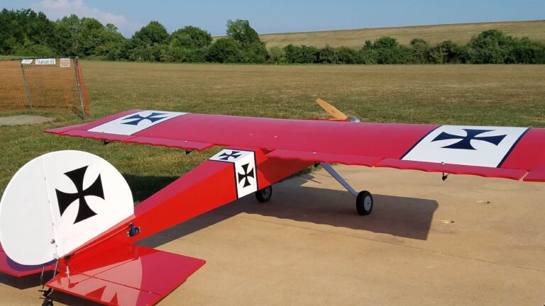
In the previous part (RC Airplane Series -1) , We learnt about the wings of the aircraft and what is the reason behind the generation of Lift for the airplane. Now that we have learnt to take the airplane into the air, it’s time to control the aircraft. So, in this part, we are going to learn how are the control surfaces used in order to control the aircraft properly.
TOPICS TO BE COVERED :
What are different control surfaces in aircraft ?
Different dimensions of movement
Aileron
Elevator
Rudder
Flaps
1. Different Control Surfaces
For the controls part, we have them divided into two parts : Primary and Secondary Control Surfaces
Primary : Ailerons, Rudder, Elevator
(These are the necessary ones! Like Air, Water and Food for us)
Secondary : Flaps
(These are the extra ones which help in controlling the aircraft more precisely) In the Secondary part, we do have some more surfaces, but for basic RC planes, Flaps are enough
Fig. Positions of Ailerons, Rudder & Elevator
2. Dimensions of Movements :
There are basically 3 axes about which movement of the aircraft happens :
Longitudinal : It goes from nose to tail of the aircraft
Lateral : It goes from wingtip to wingtip and is perpendicular to the longitudinal axis
Vertical : It is mutually perpendicular to both, longitudinal and lateral axis
Fig. Movements exhibited by an aircraft
Pitch : It is the rotational motion of the aircraft about the Lateral Axis (Nose – Up and Down)
Roll : Rotation about longitudinal axis is Roll. During this, the aircraft tilts its wing up and down
Yaw : Rotation about vertical axis is Yaw. Basically, moving right and left in the plane itself
Fig. How it exactly happens?
3. Ailerons :
– Ailerons are the control surfaces situated on the wings and are responsible for the ‘Roll’ motion of aircraft.
There are mainly 2 types of Ailerons (in Trainer Aircraft mostly) : Strip Aileron and Normal Ailerons
Strip Ailerons are the ones which span over the entire half wing and have a width = 1/8 of chord length
In normal ones, the length = 1/4 of wingspan and are situated towards wingtip and have a width = 1/4 of chord length
Working of Aileron :
For example, we need our airplane to roll towards right. For this to happen, the Right Wing should get lowered while the Left wing should be lifted up (when viewed from tail)
I will try to explain this in a very simple manner. Just remember that,
“Obstruction causes velocity to decrease“
(This is applicable for all control surfaces)
Fig. Right Aileron is raised up while Left Aileron is lowered down
Now, we want to Roll our aircraft towards right. So we control the Aileron with the help of transmitter (in case of RC Airplane), steering wheel in case of real aircrafts.
On giving the signal, the right Aileron is raised while the left Aileron is lowered down. For the moment, let’s focus on the Right Aileron. The control surface here as been moved up & now, this causes Obstruction for the Air !!
Because of this obstruction, the velocity of air in the upper part decreases and hence Pressure in the upper part increases. (refer RC Airplane Series-1) and this causes the Right wing to go down and left wing goes up and as an overall effect, we get the Roll towards right.
4. Elevator :
Elevator is connected to the horizontal stabilizer. The elevator is responsible to control the pitch of the Aircraft.
Working of Elevator :
Consider an example where we need to pitch up the plane (make the nose up !). In this case, when the signal is given, the elevator is deflected upwards. Now, again the air flow in the upper region feels an obstruction which lowers the velocity of air in upper region. This causes the Pressure in the upper region to get bigger.
This results in the ‘pressing‘ of the horizontal stabilizer downwards. Due to this the nose of the aircraft (front part) rises up.
(Just consider a pencil and hold it somewhere
Fig. Elevator is deflected upwards
The process is the same for all, whether its the aileron, elevator or the rudder
Consider an example of pencil. It’s CG (center of gravity) is marked. So when we apply a pressure on the back side (FigP(a)), the front part (part which is ahead of CG) rises up (which we say here as ‘pitch up’) as it rotates about the lateral axis passing through CG (FigP(b))
FigP(a). Pressure is applied at the back end of pencil FigP(b). Result of the application of pressure (Nose Rises)
5. Rudder :
Rudder is attached to the Vertical stabilizer. It is responsible mainly for the Yaw motion of the aircraft. Basically, Yaw is like moving right and left in your plane itself !
Working of Rudder :
Consider that we need to move shift to left while being in the plane of the aircraft (i.e. just try to give nose a different direction)
When the signal is given such that you want your nose of airplane to move towards left, then the rudder also deflects towards left. Now the rudder acts as a obstruction to the airflow on that side. Hence velocity decreased. Therefore, pressure increased. The higher pressure causes the front part to move to left (in the geometric plane)
Fig. Rudder
6. Flaps :
Flaps are the Secondary Control Surfaces which help the pilot to have a stronger control and stability over the airplane. Flaps are situated besides the Ailerons. Sometimes, the Ailerons itself work as Flaps as well (in case of single servo for each Aileron **). In this case, we call those control surfaces as ‘Flaperons’ (Flaps + Ailerons)
You must have hear pilots saying “FLAPS ON !!” or “FLAPS DOWN”. This tells that the Flaps are to be deflected downwards.
Fig. Positioning of Flaps
We are very well aware of the Lift generated because of the Flaps getting deflected downwards. (Same as Ailerons getting deflected downwards) but there is an important factor to consider, which is ‘DRAG’
DRAG :
– There is lift, but there is also DRAG developed due to downward deflection of flaps. Since, due to this, the contact between the airflow and the surface gets broken.
– This Drag causes the wing speed to decrease
For Landing, we need the plane to be slow moving since ofcourse it’s easier to handle a slow moving car than an fast one. So the drag component takes care of reducing the speed of aircraft while on the other hand we also have the Lift generated which combinedly gives a slow and controlled descent.
From takeoff point of view, we need Lift to be generated at lower speeds itself and hence Flaps are essential in this case as well.
Note that : “FLAPS UP” implies the retracting of flaps to the original position (no deflection)
The amount of deflection can be controlled based on the need with the help of control stick !!
Conclusion :
Through this article, We discussed about the Controlling of the Aircraft. Go through it slowly and try to visualize by yourself. You will definitely get it. In this Series, we will keep going step by step and gradually make the whole basic RC Airplane model. I hopw you enjoy this Series !!
Keep Learning !!
RC Airplane Series – All Articles (You are at Part – 2 !)
Commentary: Oh! we are witnessing the most exciting final ever. Just look at the score board mate! The crowd is going crazyyy at the Wankhede stadium. For now, We are having some discussion going on between captain and umpires and seems like they have been given a new ball for the last ball of the match.
Fig. Scoreboard Situation
Commentary: Till the game resumes back, we show you the stats of the players as well as the info of the Wankhede stadium.
Striker :
Age : 26
Right handed batsman
Average : 25.5
Highest : 67(36)
Maximum effort chart: (‘v’ in m/s and ‘t’ in s)
– Nature of graph : Straight line
Fig. Maximum effort chart for Striker
Non – Striker :
Age : 27
Right handed batsman
Average : 23.2
Highest : 56(23)*
Maximum effort chart: (‘v’ in m/s and ‘t’ in s)
– Nature of graph : Parabolic (It’s a curve involving some parabolas)
(This tells how a player runs between the wickets when he performs at his maximum potential and it’s a pre-recorded data)
Fig.Maximum Effort Chart for Non-Striker
Fig.Circular Shaped Wankhede Stadium
Commentary : Okay, So after a long wait, we are all ready for the play to begin !
What exactly happened?:
**The half portion of the ground (not containing the striker) is introduced with an magnetic field of upwards direction (seems as if it comes out of the ground) having magnitude 0.54 T (tesla)
Fig. What exactly happened ?
Regarding the New Ball
Mass : 160 g
Charge : 164 mC
Colour : White
Commentary : Man, I am just out of words…Just picth the ball towards the batsman, I can’t wait anymore.
So, here we go Guys !….
Match Resumes !!…It’s the last ball now
Commentary : Oh, what a excellent toe crushing yorker just ahead of the stumps, to which batsman replies with a flick towards the leg side. The ball is running towards the boundary along the ground…………….
Commentary : Both the striker and the non striker have started running with their maximum efforts across the pitch, trying their level best !!
Fig. Final Last Ball Situation
In the figure above,
v is the velocity of the ball just after the impact with the bat and theta is the angle which the ball makes with the center pitch line.
Commentary : Hey, watch out! What’s happening in here, I just can’t believe what’s happening, Also, with me, my co-commentator friends, audience as well as the players themselves are just completely astonished.
Question Parts :
(a) Why are there only 3 regions in the Maximum Effort Chart of both, striker and non-striker. Are you able to verify, if the velocity-time graphs are correct?
(b) In this scenario, can you predict What’s the result of the match!? Also, if you want, you can give some nice commentary as well to describe the situation completely.
(Assume ball to be point mass; there is no friction between ground and the ball )
Some points from my Side :
I feel that this problem is completely comprehensive based. Hint which I can give is that, Try to Extract the necessary information from the comprehension. These problems are designed to make you enjoy the subject, enjoy the process while solving. No one is there here to reduce your marks, So solve it without any hesitation !!
“I want you to be in that atmosphere as if you are an spectator seeing this match going on in front of your eyes“
RC Airplanes are fun to make and really a nice beginning step to understand Aeromodelling. This series aims to cover the aspects necessary for the modelling of RC aircraft and this will teach you can you design your own RC airplane based on your constraints/requirements !!
In this article, we are going to discuss about one of the most important aspect of the airplane, i.e. Wings.
Table of Contents
What’s the principle behind this ?
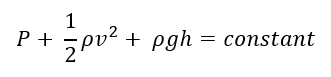
So, in order to understand about how the wings help to generate the lift, we need to know about the Bernoulli’s Principle. It states that:
” The sum of the pressure, kinetic energy density & the gravitational potential energy density at a point in streamline remains constant “
The mathematical equation for this looks like :
All this looks a bit complicated, isn’t it !?
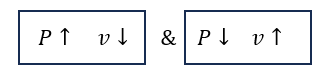
But the only thing which we require from this equation, to understand the reasoning is that :
“As pressure increases, velocity in that region decreases & vice versa is also true”
Conducting a small activity
What do we need ?
A-4 sheets x2
A quiet room (FANS OFF please !)
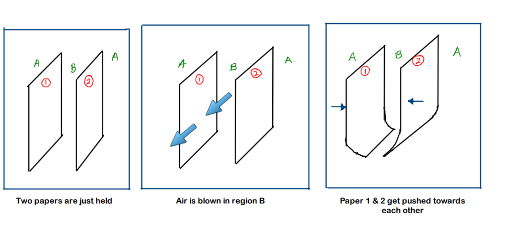
Procedure :
Hold the 2 papers vertically with each paper in each hand.
Observe that nothing happens here
Now, blow air with your mouth into the region B (region between the 2 papers)
Observe what happens !!
The step-by-step procedure & it’s result is shown in the figure below ( !! Not that good at drawing, but pls manage !! :)) )
Fig. A-4 sheets experiment procedure
Why did this exactly happen !?
Note : The region between the 2 sheets is named as ‘B’ while the region except B is called ‘region A’ (i.e. the surroundings to region B)
Initially, the pressure in region B and A is the same since the velocity of air is same everywhere
Now, we blow air into the region B (between the sheets). This causes the velocity of air in the region B to increase in comparison to its surroundings (region A)
3. Now, by Bernoulli’s principle we can derive the conclusion that,
4. Because of this, the sheets are pushed towards each other by the surroundings due to the relative higher pressure of the surroundings than that of the region B
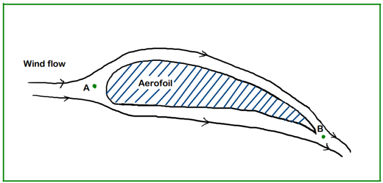
About Aerofoil Shape
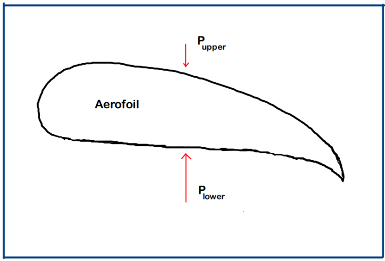
Now, to use the above results into an application, we have a shape known as ‘Aerofoil’. We can describe this shape by its upper and the lower surface. The upper surface has a curvature known as ‘Camber’ and the upper surface has larger length as compared to lower surface which is done purposely.
To understand the shape, have a look at the figure below. (I will try improving my drawing skills !!)
Fig. Aerofoil shape explanation
1. Consider points A and B. At point A, the streamlines diverge to pass over the aerofoil and then meet up again at point B. Now, we that the flow is streamlined and laminar, the air particles flowing over the upper surface have to keep up with the air particles passing under the lower surface.
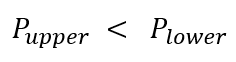
2. We already know that the upper surface has greater length as compared to lower one. Hence to meet at B at same instant, the velocity of air passing over the upper surface has to be greater since it has to cover more distance in the same time.
Hence,
But, by Bernoulli’s principle we know that,
This is how lift is generated !! & we can see that the aerofoil shape has a lot of role to play in this.
Some frequently used terms in Aerodynamics
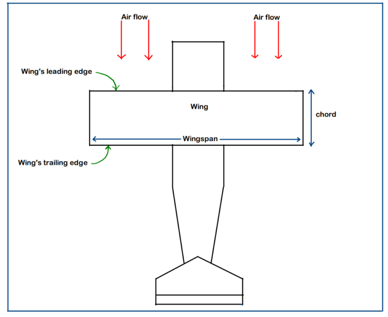
Leading Edge & Trailing Edge :
– Leading edge is the foremost edge of the wing. This is the first part of the wing which comes in contact with the air flow. It is mostly rounded in order to have a smooth airflow over the wing.
– Trailing edge is the rearmost edge of wing. This is the portion where the airflow leaves the wing. This edge of the wing includes the control surfaces with Ailerons and the Flaps
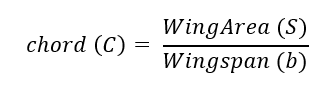
Chord :
– The distance (straight line length) between the leading edge and the trailing edge of the wing is called ‘chord’.
– It is not always that the wing will be rectangular, so, in that case we consider the ‘mean’ chord length which can be calculated based on the shape of the wing.
– For rectangular wing, the width of the rectangle becomes the chord.
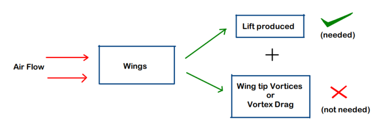
Vortex Drag :
– Now, this is something which comes as a by-product with the ‘Lift’ which we don’t need and hence we must try to atleast minimize it as much as possible.
Fig. explanation : When the air flows over the Wings, lift is generated & simultaneously, wing tip vortices are also formed which we need to minimize since it consumes fuel, hence dropping the fuel efficiency of plane.
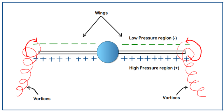
Why does it happen ?
– The wing is an finite dimension part and hence it will come to an end at some point. This is the point which we call as
‘Wing tip’. Just at the wing tips, there is still a high pressure region below and a low pressure region above. This pressure difference causes the air particles to execute a rotational type of motion which we call ‘vortex’
Now due to this, 1. The air particles exhibit rotational motion (as we see in the figure)
2. But from where do these particles get energy to exhibit this rotational motion
3. This energy is extracted from the wings (or indirectly, the part of the fuel is getting consumed to overcome this drag)
4. Therefore, we conclude that, the induced drag affects the fuel efficiency of airplane
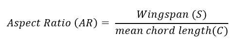
Aspect Ratio (AR):
– Aspect Ratio is defined as the ratio of the wingspan to the mean chord length
– It is one of the most characteristic of the object (here airplane) and AR for an aircraft is determined based on the work it is going to be used for.
For example,
– High Aspect Ratio : Used to have more fuel efficiency for aircraft (due to lesser induced drag)
– Moderate Aspect Ratio : Used to get the benefits of both : maneuverability & fuel efficiency
– Low Aspect Ratio : Used to get more maneuverability (ability to change direction)
Wingspan is everything !
While designing the RC airplane, the first most important thing which you need to fix, is the ‘Wingspan’ of your aircraft. Wingspan is nothing but the length of your wing (including fuselage width).
Generally, while designing the RC Aircraft, we have a fixed set of ratios defined which tell us what all dimensions should different parts/components of airplane have.
For examples, we take some ratios like: (We fix Wingspan = 1m)
1. The fuselage length = 75% of wingspan
= 75 % of 100cm
= 75 cm
2. Now for Trainer Aircraft, Aspect Ratio is 5:1
hence, chord = wingspan/5
= 100/5
= 20cm
3. Aileron length has to be 1/4th of wingspan
Aileron length = (1/4) x wingspan
= (1/4) x 100cm
= 25cm
We can clearly see that in all calculations, somehow or the other, ‘Wingspan’ is getting involved.
There are still many dimensions you can calculate directly/indirectly using wingspan…
Conclusion
To conclude this post, we learnt about the basic working principles of wings. Just making an RC Airplane is one thing while Understanding the RC Airplane is another thing. We are going to focus on the understanding part first which will surely make our further work much more easier + the additional satisfaction that we know the reasoning behind what we are doing !!
Till then, Keep Learning & Enjoy the Process !!
RC Airplane Series – All Articles (You are at Part-1 !)