For Best Experience, View on Desktop/Laptop !

In the Part-1 : Learning about Capacitors, We already got an idea about the functioning of the capacitors. But now, with that understanding, how to make use of them in electric circuits !?
This is what we focus in this article. Getting inclined towards the numerical aspect of the capacitors is our goal for this article !!
Topics to be Covered :
- Clearing the basics
- Parallel Plate Capacitors
- What is dielectric & it’s use ?
- Series & Parallel Combination
- Circuit simplifying methods
- Special Equivalent capacitance problem
1. Clearing the basics
As discussed in part-1, more the charge separation happens (+Q on one plate and -Q on other), more will be the potential difference across the plates of capacitor(V). So basically we can say,

Now we introduce the ‘constant’ of proportionality –> Capacitance (C). The relation becomes :

Note that :
- Increasing the charge doesn’t increase it’s capacitance of the capacitor as it may appear in above equation. For simplicity remember it as –> Once a capacitor is made, it’s capacitance value is stamped on it !!
- Instead, capacitance is decided by the physical dimensions and the dielectric used. (For understanding, once the vessel is manufactured, it has some dimensions to it and based on that dimensions, you can decide the capacity of vessel)
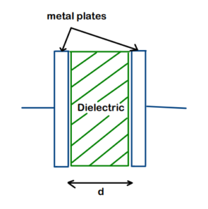
2. Parallel Plate Capacitors
There are many configurations possible to make a capacitor, but the most simplest one to analyze is the Parallel plate Capacitor. This setup basically consists of :
- 2 metal plates of area ‘A’ kept at a distance ‘d’ apart from each other
- Dielectric medium (of dielectric constant ‘k’) inserted in between the plates
- Important Condition : (A>>d)
The capacitance of the parallel plate capacitor is given by :

We can clearly verify from the above expression that, the capacitance just depends upon the geometrical factors and the dielectric constant.
*Interested readers can have a look at the derivation of the above expression in document attached at the end of the article or can download the file directly
Click here to download the file – DOWNLOAD
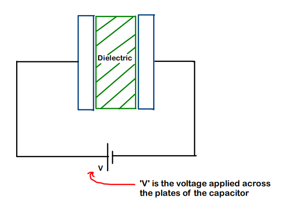
3. What is dielectric & it’s use ?
“In simple words, Dielectric are a type of insulating materials which allow Electric field but don’t allow electric current to pass through them”
They are majorly used to serve 3 purpose:

It is necessary to maintain the gap (even though small) between the metal plates. Because, the capacitor would loose all of it’s storing capacity if the metal plates come in contact with each other; since in that case, it would just behave as a simple conductor.
-
Increasing max. voltage without breakdown
Dielectric Breakdown :
- Each dielectric material has it’s own breakdown voltage.
- If the applied voltage becomes greater than the breakdown voltage of the dielectric material, the atoms start to get ionized and we know that , ions do conduct electricity.
- Because of this, the whole capacitor starts to act as a conductor
Better the dielectric material, more will be the dielectric breakdown voltage. Let’s consider 2 situations :
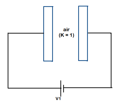
Situation-1 (Air between plates)
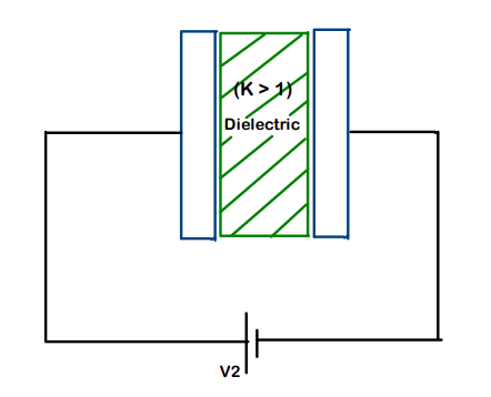
Situation – 2 (Dielectric material D2 inserted between plates)
The dielectric breakdown voltage of material (say D2) is more than that of air. This implies that more voltage across capacitor plates is required in case of D2 for breakdown to happen. This proves our point that, the insertion of dielectric allows us to apply more voltage across capacitor plates without causing any dielectric breakdown.
Suppose we have a capacitor with just air between the plates. Now we insert a dielectric material of dielectric constant ‘k’ between the plates completely. Have at the look at the flowchart below to just get an quick overview of what happens !

Flowchart – Summary of how Dielectrics help to increase Capacitance
4.1 Series Combination in Capacitors
“Like the way we have current in case of resistors, in the same way, for capacitors, we have charge”
- For Capacitors to be said in Series combination, the charge flowing through them should be the same.
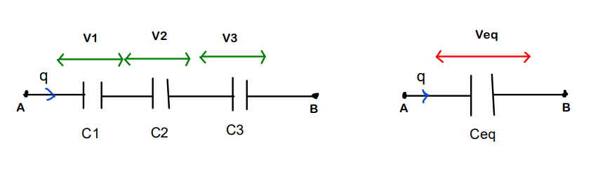
Consider 3 capacitors C1, C2 and C3 in series combination and V1, V2 and V3 are the potential differences across them respectively.
Since we need to find the ‘equivalent’ capacitance :

So, we can observe that, by keeping capacitors in series, we get the value of equivalent or resultant capacitance which is even lesser than the one which has least capacitance among the three. Suppose, C2 < C1 < C3, then Ceq < C2
4.2 Parallel Combination in Capacitors
Again : “Like the way we have current in case of resistors, in the same way, for capacitors, we have charge”
- For the Capacitors to be in Parallel, the potential difference across all should be same.
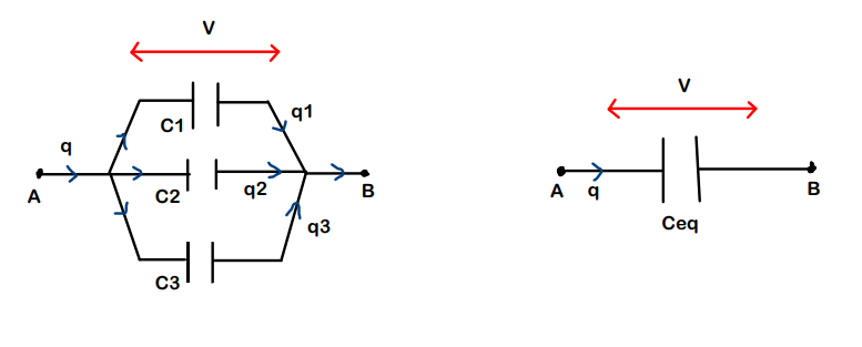
Consider 3 Capacitors C1, C2 and C3 in parallel combination and the charges passing through them are q1, q2 and q3 respectively.
We know the relation from KCL :

The equivalent capacitance incase of parallel combination will be greater than the greatest among the three (here)
5. Circuit simplifying methods
Now, there are again some types of network circuits in which we are expected to find the equivalent Capacitance.
There are several methods to simplify and solve such type of circuits like :
- Mirror Symmetry
- Folding symmetry
- Voltage method (Rearrangement)
We have already looked at the above methods with context to resistors in Part-2 : Combining Resistors
Though the article is for Resistors, the approach of simplifying the circuit/network still remains the same !

6. Special equivalent capacitance problem :
Example :
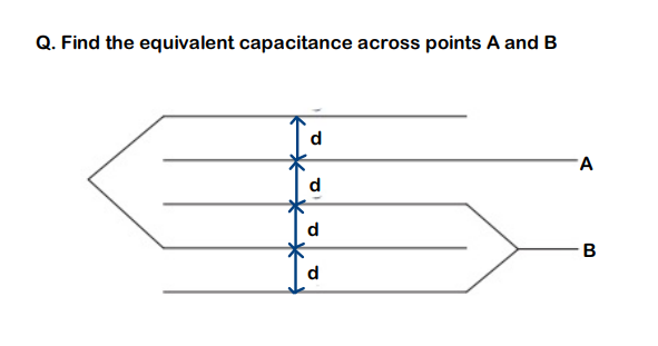
Step-1 :
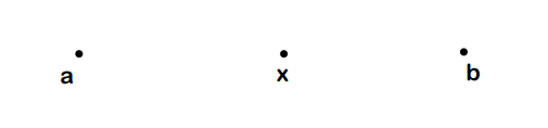
Distribute the voltages across all plates. In this example we consider the voltage/potential at A to be ‘a’ and at B, to be ‘b’. Still we are not able to cover all the plates. So we introduce another unknown potential ‘x’
Remember that : Potential always remains constant on a conductor

Step-2 :
Assign the numbers to each face of the plates
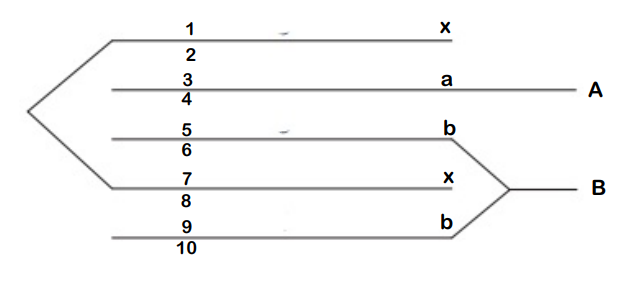
Step-3 :
Keep points ‘a’ and ‘b’ at the ends and all the unknowns which we introduced should come in between.
Step-4 :
To make a capacitor, we need 2 plates and separate them by a distance
- Faces 2 and 3 make a capacitor
- Faces 4 and 5 make a capacitor
- Faces 6 and 7 make a capacitor
- Faces 8 and 9 make a capacitor
So, now, we just look at the numbers assigned to their faces and make a simlified circuit

Step-5 :
Solve by normal Series- Parallel concepts
The equivalent capacitance of the simplified circuit is 5C/3, where C is :

Conclusion :
- Just Combining these 2 components – Resistors and Capacitors opens up a whole new set of things that can be developed. We will be looking into these in our upcoming articles.
Till then, Keep Learning !
Attached Document : Reference for Derivation of Capacitance for Parallel Plate Capacitors
DOWNLOAD
Reference - Capacitor Derivation